Cluster-based cache memory allocation

a cache memory and cluster technology, applied in the direction of memory address/allocation/relocation, instruments, computing, etc., can solve the problems of wasting valuable data storage space in the cache memory, inefficient configuration of segments, etc., and achieve the effect of increasing the length of the original assigned segmen

Inactive Publication Date: 2006-02-07
WESTERN DIGITAL TECH INC
View PDF4 Cites 134 Cited by
  • Summary
  • Abstract
  • Description
  • Claims
  • Application Information

AI Technical Summary

Benefits of technology

[0008]The invention may be embodied in a disk drive, and related method, for servicing host disk commands using a cache memory having a plurality of sequentially-ordered memory clusters for caching disk data of disk sectors identified by logical block addresses. The disk drive includes a cache control system having a plurality of cluster control blocks and a tag memory usable only for providing a plurality of tag records. Each cluster control block has a cluster segment record for associating the cluster control block with a particular memory cluster and for forming variable length segments of the memory clusters without regard to the sequential order of the memory clusters. Each tag record assigns a segment to a contiguous range of logical block addresses and defines the cluster control blocks forming the segment. Each segment of the memory clusters is for caching disk data of the assigned contiguous range of logical block addresses.
[0009]In more detailed features of the invention, the cluster segment record of each cluster control block associated with a segment may include a pointer to a subsequent cluster control block or to indicate an end cluster control block of the segment. Each tag record may define a length for the assigned segment by pointing to a first cluster con

Problems solved by technology

The memory segments may be inefficiently configured to order to accommodate host commands having a long LBA

Method used


Image

  • Cluster-based cache memory allocation
  • Cluster-based cache memory allocation
  • Cluster-based cache memory allocation

Examples


Embodiment Construction

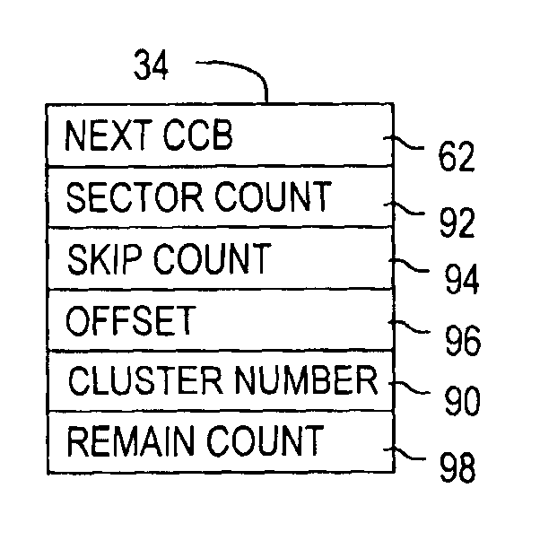
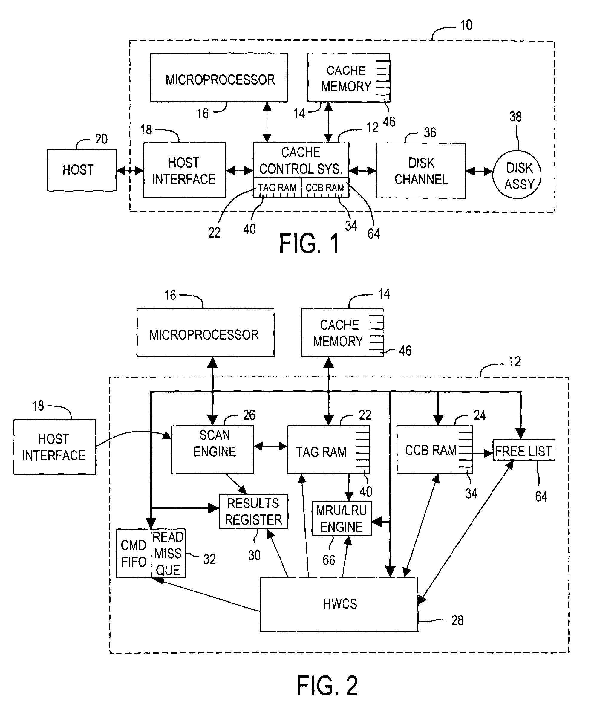
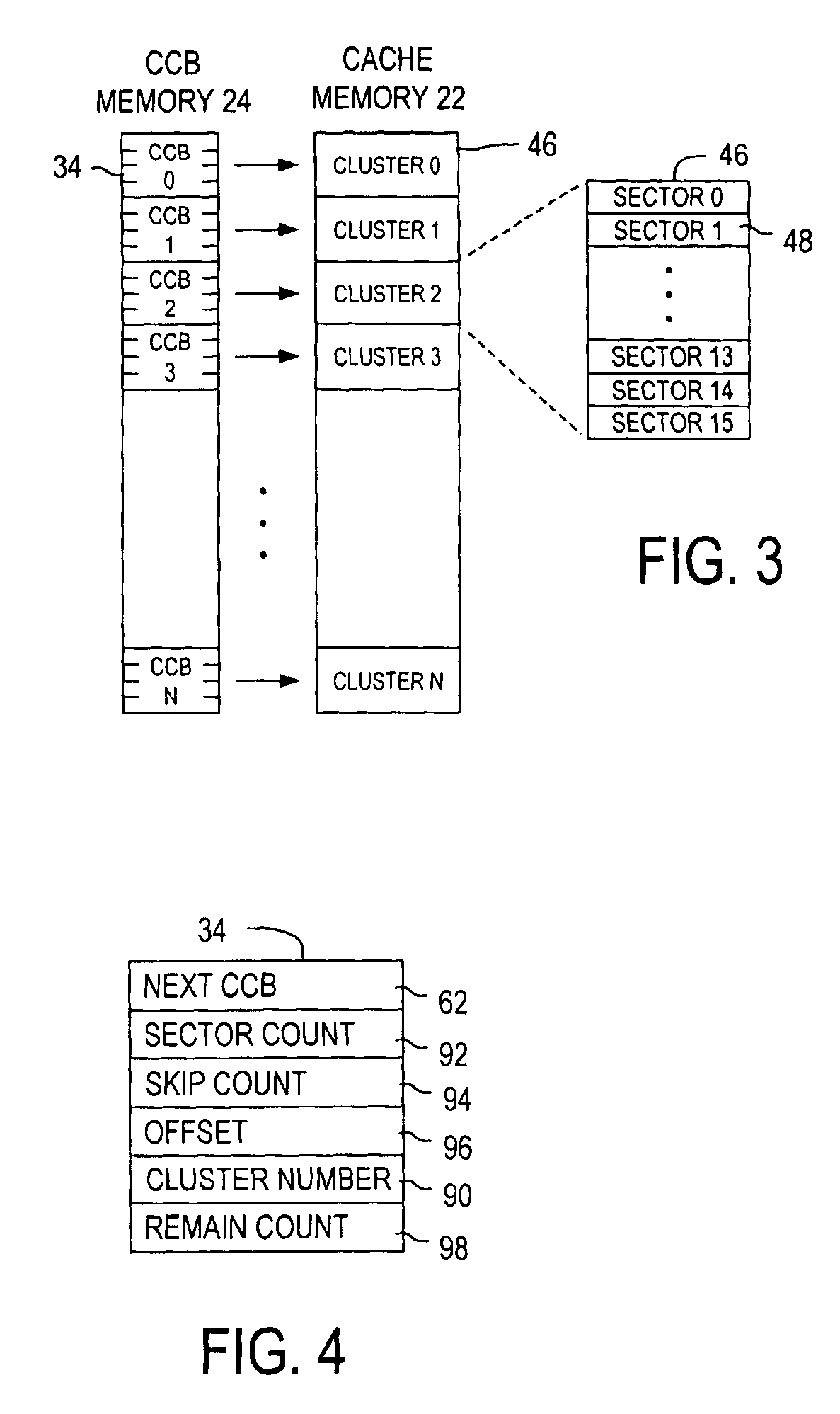
[0020]With reference to FIG. 1, a disk drive 10 comprises a cache memory 14 having a plurality of sequentially-ordered memory clusters 46 for caching disk data stored in sectors (not shown) on disks of a disk assembly 38. Conventionally the disk sectors are identified by logical block addresses (LBAs). A cache control system 12 of the disk drive 10 comprises a cluster control block memory, having plurality of cluster control blocks (CCBs) 34, and a tag memory 22, having a plurality of tag records 40, that are embedded within the cache control system 12. Each CCB 34 includes a cluster segment record with an entry 90 (FIG. 4) for associating the CCB 34 with a particular memory cluster 46 and for forming variable length segments of the memory clusters 46 without regard to the sequential order of the memory clusters 46. Each tag record 40 assigns a segment to a continuous range of LBAs and defines the CCBs 34 forming the segment. Each segment of the memory clusters 46 is for caching dat...


PUM


Abstract

The present invention relates to a disk drive including a cache memory having a plurality of sequentially-ordered memory clusters for caching disk data stored in sectors (not shown) on disks of a disk assembly. The disk sectors are identified by logical block addresses (LBAs). A cache control system of the disk drive comprises a cluster control block memory, having a plurality of cluster control blocks (CCB), and a tag memory 22, having a plurality of tag records, that are embedded within the cache control system. Each CCB includes a cluster segment record with an entry for associating the CCB with a particular memory cluster and for forming variable length segments of the memory clusters without regard to the sequential order of the memory clusters. Each tag record assigns a segment to a continuous range of LBAs and defines the CCBs forming the segment. Each segment of the memory clusters is for caching data from a contiguous range of the logical block addresses. The cache control system efficiently exploits available memory clusters for responding to host commands.

Description

[0001]This application is a continuation of application No. 09 / 552,407, filed Apr. 19, 2000, now Pat. No. 6,606,682, herein incorporated by reference.BACKGROUND OF THE INVENTION[0002]1. Field of the Invention[0003]The present invention relates to disk drive performance features, and more particularly to a disk drive having a cache control system for improving the disk drive's response time to host commands.[0004]2. Description of the Prior Art[0005]A host computer stores and accesses data on a disk drive by issuing commands to the disk drive over a standardized interface. The smallest indivisible data unit addressable on a disk is a logical block or disk sector, typically of 512 bytes, and each such disk sector is assigned a logical block address (LBA). When the host computer sends a command to the disk drive, the nature of the command is specified, e.g., read or write, along with a start LBA and a count specifying the number of contiguous sectors to be transferred.[0006]Existing di...

Claims


Application Information

Patent Timeline
IPC IPC(8): G06F12/00G06F12/08
CPCG06F12/0873G06F2212/313G06F2212/312
Inventor DANG, QUOC N.NG, TSUN Y.CASTRO, RALPH H.WILKINS, VIRGIL V.
Owner WESTERN DIGITAL TECH INC
Why Eureka
Try Eureka