
Millimeter wave (MMW) transceiver module with transmitter, receiver and local oscillator frequency multiplier surface mounted chip set

a technology of micro-wave monolithic integrated circuits and transceivers, applied in the direction of transmission, basic electric elements, association of printed circuit non-printed electric components, etc., can solve the problems of high volume production of mmic chips, tight tolerances required for manufacturing such components, and difficulty in working with fragile mmic chips, etc., to achieve low cost

Inactive Publication Date: 2006-02-14
REVEAL IMAGING
View PDF22 Cites 16 Cited by
  • Summary
  • Abstract
  • Description
  • Claims
  • Application Information

AI Technical Summary

Benefits of technology

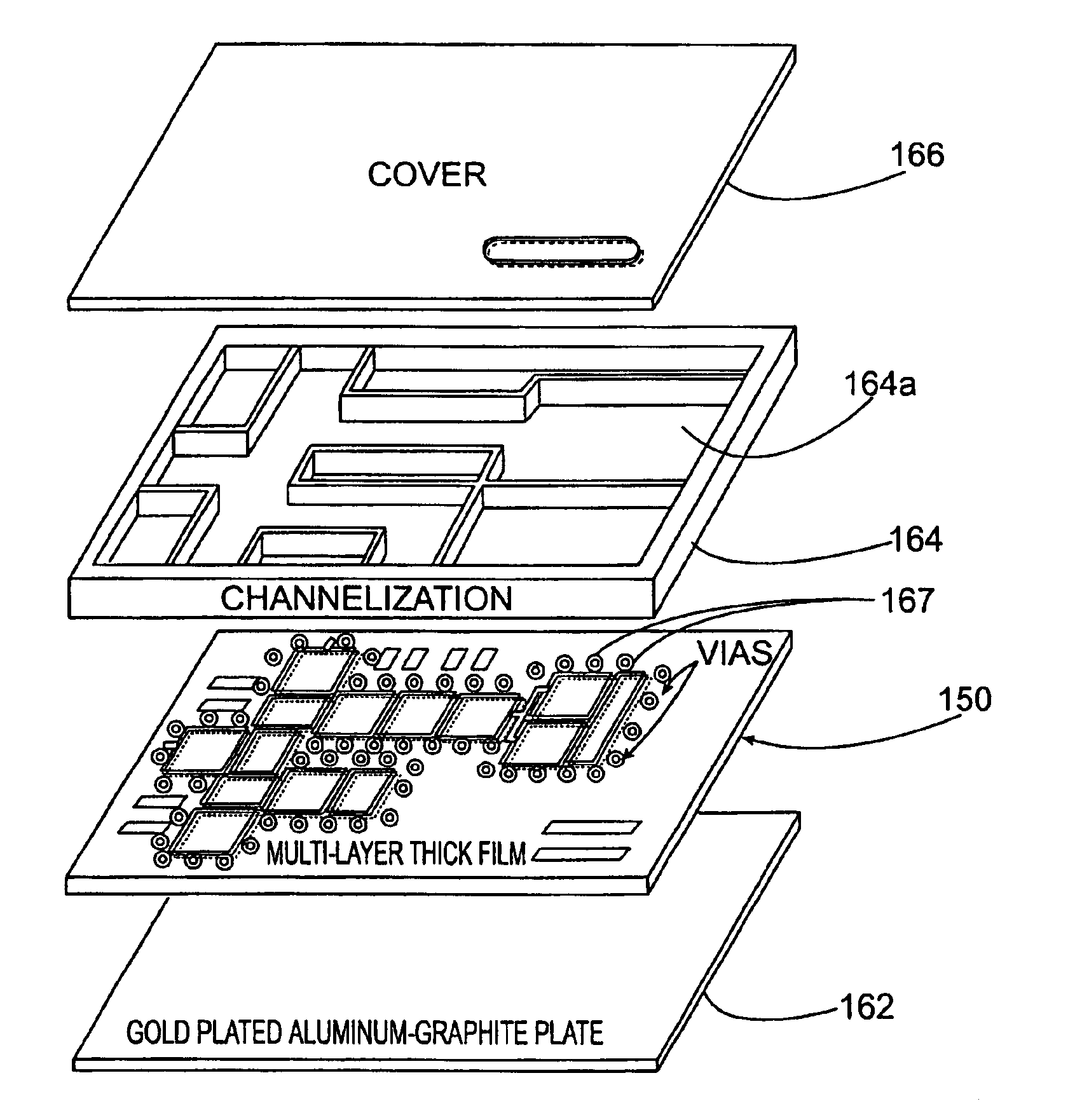
[0008]The present invention advantageously overcomes the prior art drawbacks and provides a millimeter wave (MMW) transceiver module and method of fabricating same by using a low cost microwave monolithic integrated circuit (MMIC) transceiver chip set that is surface mounted on a circuit board, such as a printed circuit

Problems solved by technology

The key elements that prevented this technology from attaining high volume production, similar to surface mount technology components, is the difficulty in working with fragile MMIC chips and the tight tolerances required when manufacturing such components.
Although many chip manufacturers are now offering individual MMIC chips in a surface mount package, an entire receiver, transmitter or local oscillator (LO) multiplier have not been provided in a single chip package to enable production of a MMW module with fewer surface mounted components.
In addition, the unavailability of a wide array of surface mount MMIC chips has caused designers to shy away from their use because of the requirement to mix bare die with surface mount chips.
Another reason why single transmitter, receiver or LO multiplier MMIC chip packages have not been available is because these types of devices require some level of filtering of unwanted signals.
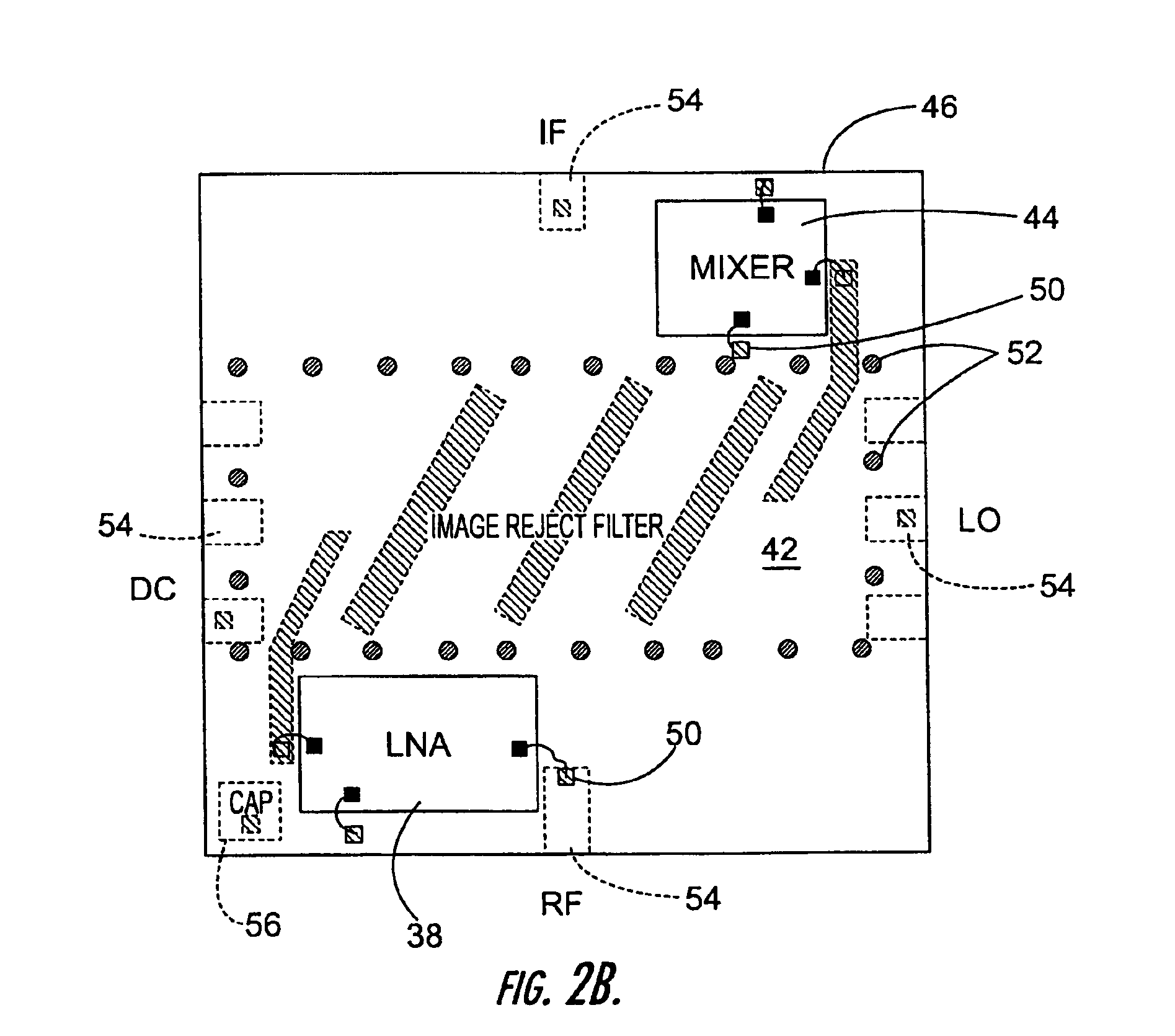
Prior art filters used in conjunction with such devices were traditionally made from thin film material, and were too large to mount into a small chip package.
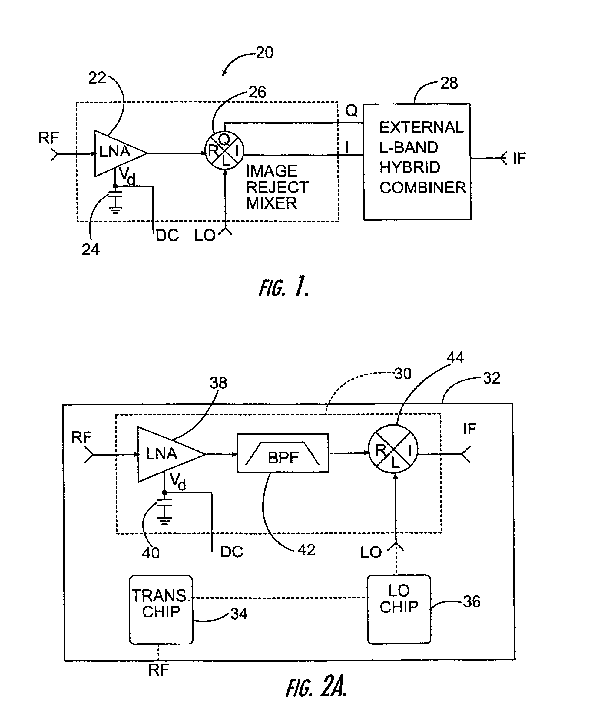
These receiver chips have not seen wide commercial acceptance because of their limited image reject performances and the requirement to use an external I / Q hybrid combiner 28 to obtain a single IF output.

Method used


Image

  • Millimeter wave (MMW) transceiver module with transmitter, receiver and local oscillator frequency multiplier surface mounted chip set
  • Millimeter wave (MMW) transceiver module with transmitter, receiver and local oscillator frequency multiplier surface mounted chip set
  • Millimeter wave (MMW) transceiver module with transmitter, receiver and local oscillator frequency multiplier surface mounted chip set

Examples


Embodiment Construction

[0029]The present invention will now be described more fully hereinafter with reference to the accompanying drawings, in which preferred embodiments of the invention are shown. This invention may, however, be embodied in many different forms and should not be construed as limited to the embodiments set forth herein. Rather, these embodiments are provided so that this disclosure will be thorough and complete, and will fully convey the scope of the invention to those skilled in the art. Like numbers refer to like elements throughout.

[0030]The present invention is advantageous and uses advances in multilayer, low temperature, co-fired ceramic, thick film technology to provide an advanced design and efficient fabrication of a microwave monolithic integrated circuit (MMIC) transceiver module by providing a low cost MMIC transceiver chip set, including receiver, transmitter and local oscillator multiplier chip packages that measure only about 0.2 by 0.25 inches, in one aspect of the prese...


PUM


Abstract

A millimeter wave (MMW) transceiver module includes a microwave monolithic integrated circuit (MMIC) transceiver chip set that is surface mounted on a circuit board. The MMIC transceiver chip set includes a receiver MMIC chip package, a transmitter MMIC chip package, and a local oscillator (LO) multiplier MMIC chip package. Each MMIC chip package includes a base and a multilayer substrate board formed from layers of low temperature transfer tape. The multilayer substrate board has at least three layers and carries RF signals, DC signals, grounding and embedded passive components, including resistors and capacitors. At least one MMIC chip is received on the multilayer substrate board.

Description

RELATED APPLICATION[0001]This application is a continuation of Ser. No. 10 / 053,239 filed Jan. 15. 2002 now U.S. Pat. No. 6,627,992 which is based on provisional patent application Ser. No. 60 / 292,389 filed May 21, 2001, the disclosure of which is hereby incorporated by reference in its entirety.FIELD OF THE INVENTION[0002]This invention relates to microwave monolithic integrated circuit (MMIC) radio frequency modules, and more particularly, this invention relates to a millimeter wave (MMW) transceiver module using microwave monolithic integrated circuit (MMIC) chip packages.BACKGROUND OF THE INVENTION[0003]Microwave monolithic integrated circuits (MMIC) used in radio frequency (RF) modules have traditionally been built in low to medium volume. The key elements that prevented this technology from attaining high volume production, similar to surface mount technology components, is the difficulty in working with fragile MMIC chips and the tight tolerances required when manufacturing su...

Claims


Application Information

Patent Timeline
IPC IPC(8): H01L23/34H01L23/367H01L23/538H01L23/66H04B1/18H04B1/40H05K1/02H05K1/18
CPCH01L23/3677H01L23/5383H01L23/5385H01L23/66H01L2224/48227H01L2924/09701H01L2924/16152H01L2924/16195H04B1/18H04B1/40H05K1/0243H05K1/181H01L2224/48091H01L2924/00014
Inventor AMMAR, DANNY F.
Owner REVEAL IMAGING
Learn More