
Component operating with bulk acoustic waves and a method for producing the component

a technology of acoustic waves and components, applied in the direction of generators/motors, piezoelectric/electrostrictive transducers, transducer types, etc., can solve the problems of affecting the functionality of the entire component, the structure method of generating flat edges or, respectively, is not always possible, and the use of thicker layers is complicated. , to achieve the effect of reducing the height difference in the stacked structure of the acoustic mirror,

Active Publication Date: 2006-02-14
SNAPTRACK
View PDF16 Cites 120 Cited by
  • Summary
  • Abstract
  • Description
  • Claims
  • Application Information

AI Technical Summary

Benefits of technology

[0006]It is an object of the present invention to provide a component operating with bulk acoustic waves with a structured mirror layer that prevents the problems mentioned hereinabove.
[0010]In an advantageous modification of the invention, it is possible to structure a plurality of mirror layers with a high acoustic impedance in order to reduce the undesired capacitive coupling between different thin-film resonators arranged on the acoustic mirror via further conductive high-impedance layers of the acoustic mirror.
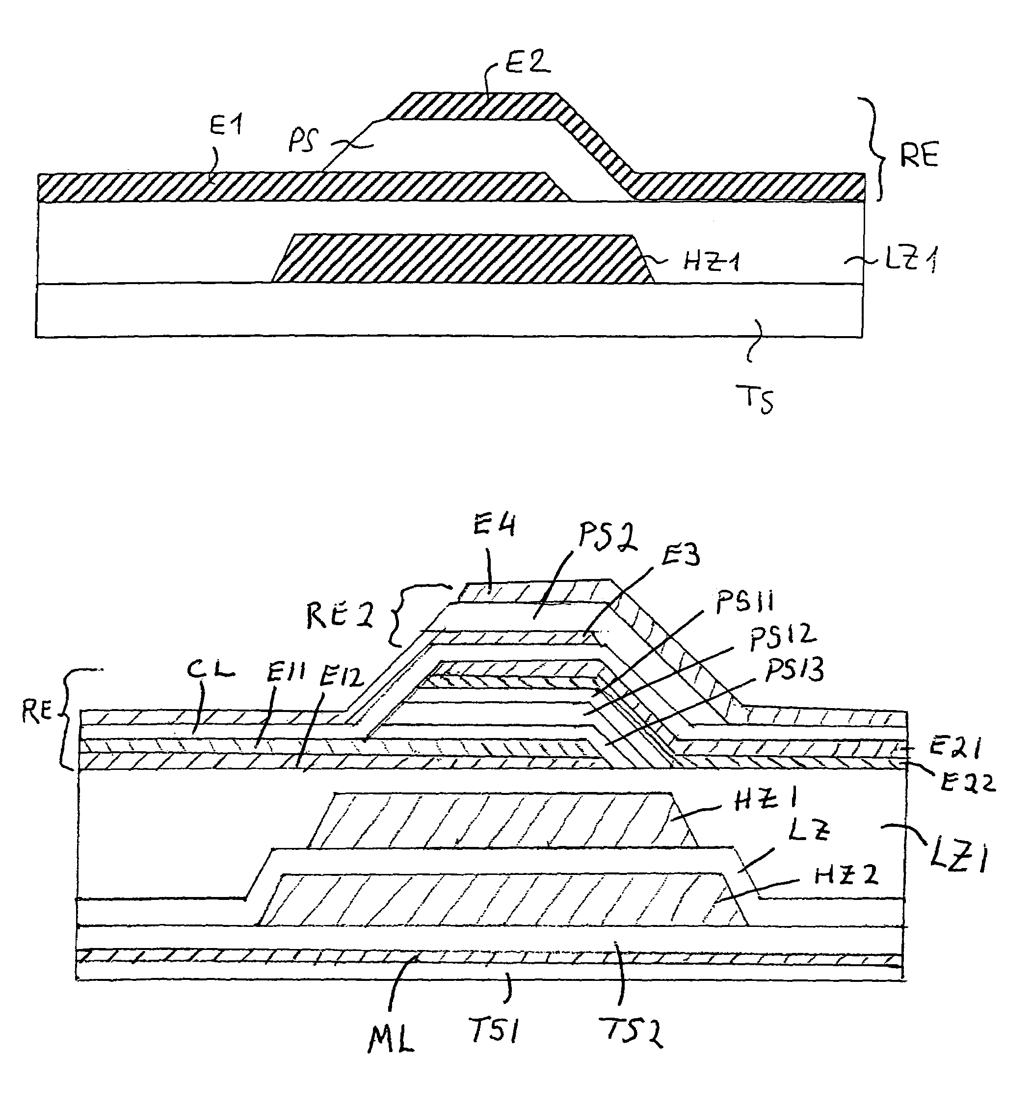
[0015]Compared to previous known bulk acoustic wave components with structured mirror layers, the invention offers the advantage that the surface of the acoustic mirror is planarized, which makes processing of the layers of the thin-film resonator easier and contributed to the reliability of the component. Wet-chemical etching methods can be cost-effectively used to structure the high-impedance layers. The abandonment of the structuring of the low-impedance layers offers the advantage that the height difference in the stacked structure of the acoustic mirror is kept low, which makes the planarization easier.

Problems solved by technology

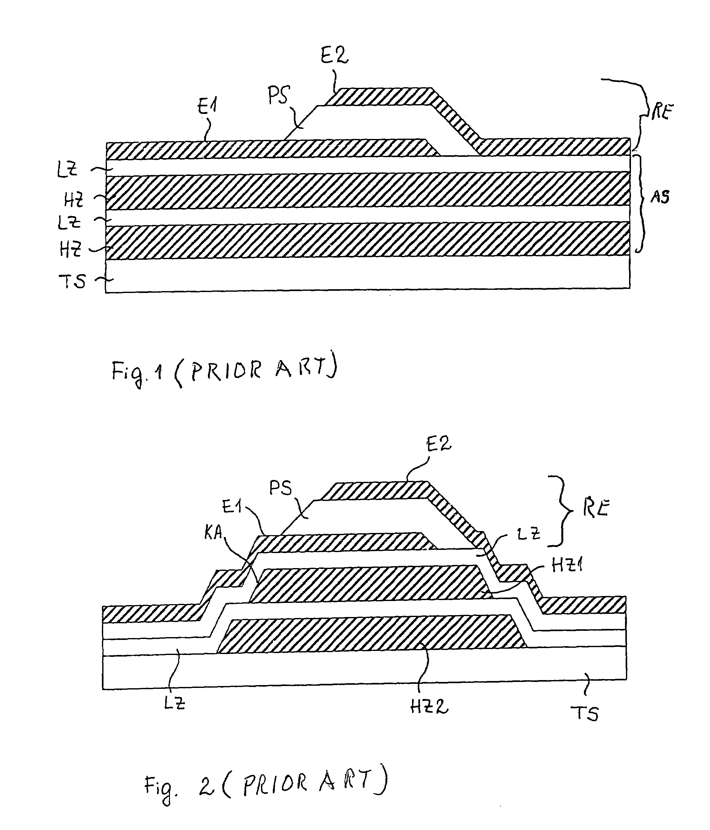
The discontinuities of the structure formed by the edges KA can, as the case may be, lead to interruptions or breaks of the layers arranged above them and, thus, impair the functionality of the entire component.
A structuring method to generate flat edges or, respectively, the use of thicker layers is not always possible, for technological reasons or reasons of design technology.
However, this method has the disadvantage that an elaborate dry etching or different wet etching methods for high-impedance layers or for the low-impedance layers are necessary to structure the entire stack of layers.

Method used


Image

  • Component operating with bulk acoustic waves and a method for producing the component
  • Component operating with bulk acoustic waves and a method for producing the component
  • Component operating with bulk acoustic waves and a method for producing the component

Examples


Embodiment Construction

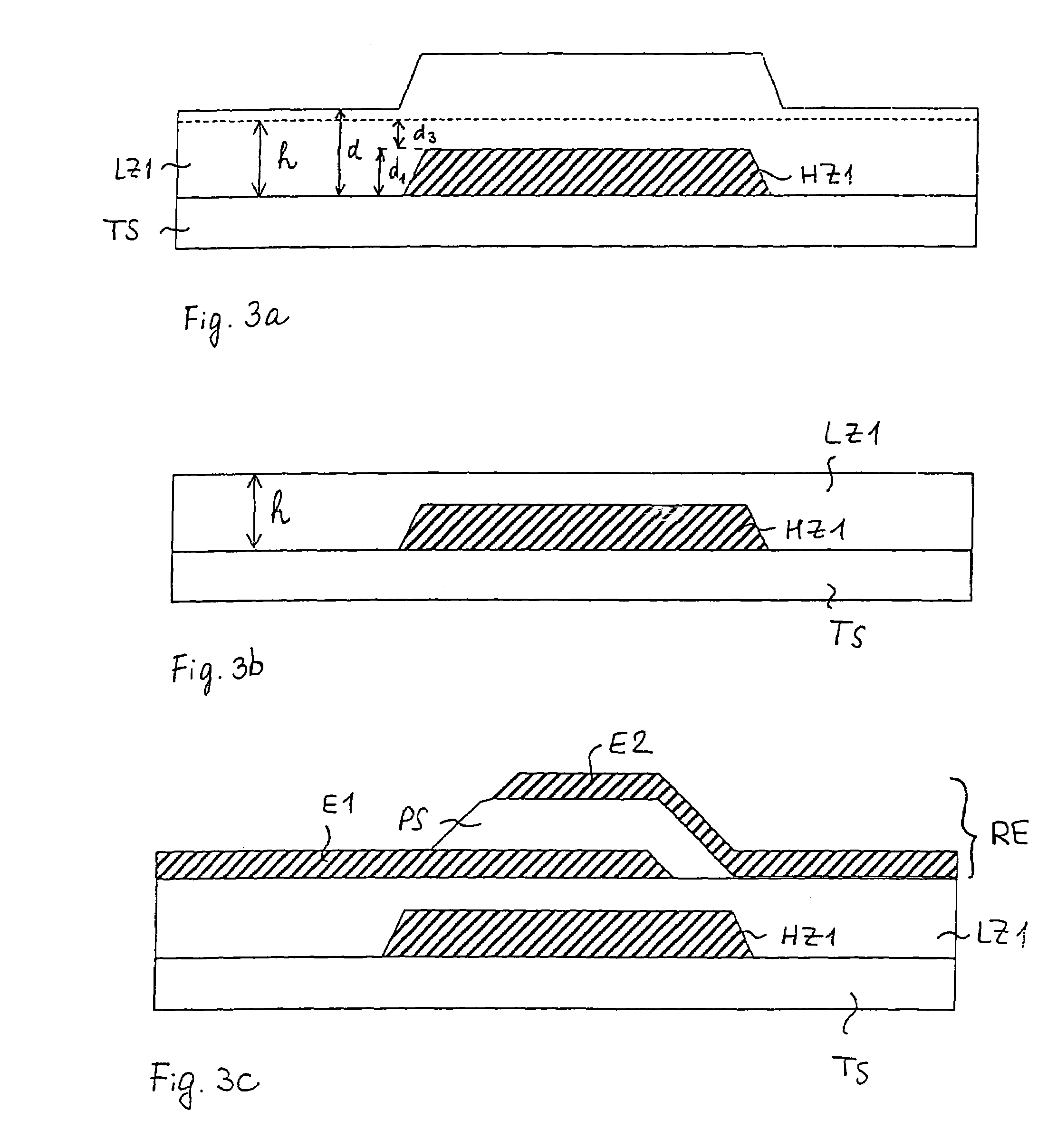
[0022]The principles of the present invention are particularly useful when incorporated in a component which has a two-layer acoustic mirror and is formed by the steps shown in FIGS. 3a–3c.

[0023]As illustrated in FIG. 3a, an acoustic mirror, which comprises a structured mirror layer HZ1 with a high acoustic impedance is disposed on a substrate TS and the structured layer HZ1 is covered by a mirror layer LZ1 of a low acoustic impedance. The uppermost mirror layer LZ1 is shown before the planarization of this layer and the height or thickness of the mirror layer LZ1 varies in the lateral direction. The height or thickness d, which is the minimum thickness of the layer LZ1 when it is applied, is no smaller than the total height or thickness h of the layer LZ1 after planarization. It is also possible that d is selected equal to h. The height h measures the sum of the thickness d1 of the structured mirror layer HZ1 and the minimum provided thickness d3 of the layer LZ1 directly above th...


PUM

PropertyMeasurementUnit
Acoustic impedanceaaaaaaaaaa
Electric impedanceaaaaaaaaaa

Abstract

A component operating with bulk acoustic waves has a carrier substrate, a thin-film resonator and an acoustic mirror arranged between the resonator and carrier substrate. The acoustic mirror is formed by at least one high acoustic impedance layer, which is covered by a low acoustic impedance layer and the uppermost low impedance acoustic layer is planarized to form a flat planar surface on which the thin-film resonator is formed.

Description

BACKGROUND OF THE INVENTION[0001]The present invention is directed to a component operating with bulk acoustic waves that comprises a thin-film resonator, which may be called a bulk acoustic wave resonator (BAW resonator) or a thin-film bulk acoustic wave resonator (FBAR). The invention is also directed to a method for producing this component.[0002]Thin-film resonators play a role as filters for terminals or end devices for mobile telecommunication.[0003]A thin-film resonator RE is schematically shown in FIG. 1 and comprises two electrodes E1 and E2 with a piezoelectric layer PS arranged between them. The thin-film resonator RE is arranged on a carrier substrate TS. It is possible to arrange the thin-film resonator over a recess provided in the carrier substrate. The propagation in the direction of the carrier substrate of the acoustic waves generated in the resonator is thereby prevented by the recess. Another possibility, as illustrated in FIG. 1, is to arrange an acoustic mirror...

Claims


Application Information

Patent Timeline
IPC IPC(8): H03H9/54H03H3/02H03H9/15H03H9/02H03H9/17H03H9/58
CPCH03H3/02H03H9/02125H03H9/584H03H9/589H03H9/175Y10T29/42
Inventor METZGER, THOMAS
Owner SNAPTRACK
Learn More