
Method and apparatus for controlling an internal combustion engine using combustion chamber pressure sensing

a technology of pressure sensing and internal combustion engine, which is applied in the direction of engine ignition, braking system, position/direction control, etc., can solve the problems of subsequent engine damage, difficult control of ignition of such charges in internal combustion engine, and excessive pressure oscillation

Inactive Publication Date: 2006-02-21
WESTPORT POWER
View PDF68 Cites 48 Cited by
  • Summary
  • Abstract
  • Description
  • Claims
  • Application Information

AI Technical Summary

Benefits of technology

This approach provides precise control over SOC, improving combustion efficiency, reducing engine knock, and minimizing pollutant emissions by ensuring consistent auto-ignition across all engine cylinders, thus enhancing engine performance and reducing system complexity.

Problems solved by technology

Controlling ignition of such charges in an internal combustion engine can be difficult, however.
Early ignition of a premixed charge during the compression stroke of the piston can result in overpressure, excessive pressure oscillations (typically referred to as engine knock) and subsequent engine damage.
However, by limiting the compression ratio and restricting how fuel-lean the premixed charge can be prepared, the performance of the engine can also be limited and result in combustion that can be more polluting than is the case for combustion arising from auto-ignition of a fuel-air mixtures that is prepared with a fuel to air ratio below the theoretical lean propagation limit.
This, however, can affect the engine operating load range.
Other strategies affect performance, increase system complexity, and / or increase costs.
An important issue with PCCI-DI engines is the control of combustion phasing, herein referred to as controlling the start of combustion (SOC) of the premixed charge.
The effect of each variable upon the evolution of mixture state results in an onset of combustion that is less easily predicted and controlled.

Method used


Image

  • Method and apparatus for controlling an internal combustion engine using combustion chamber pressure sensing
  • Method and apparatus for controlling an internal combustion engine using combustion chamber pressure sensing
  • Method and apparatus for controlling an internal combustion engine using combustion chamber pressure sensing

Examples


Embodiment Construction

)

[0044]A method is provided for calculating the SOC of a premixed charge of air and fuel within a combustion chamber of an internal combustion engine and applying that method to control SOC of a premixed charge of fuel subsequently introduced into the combustion chamber of an internal combustion engine.

[0045]Further, a method to affect the auto-ignition properties of a premixed charge of air and fuel by controlling the quantity and stratification of a relatively easy to auto-ignite fuel into the charge is disclosed.

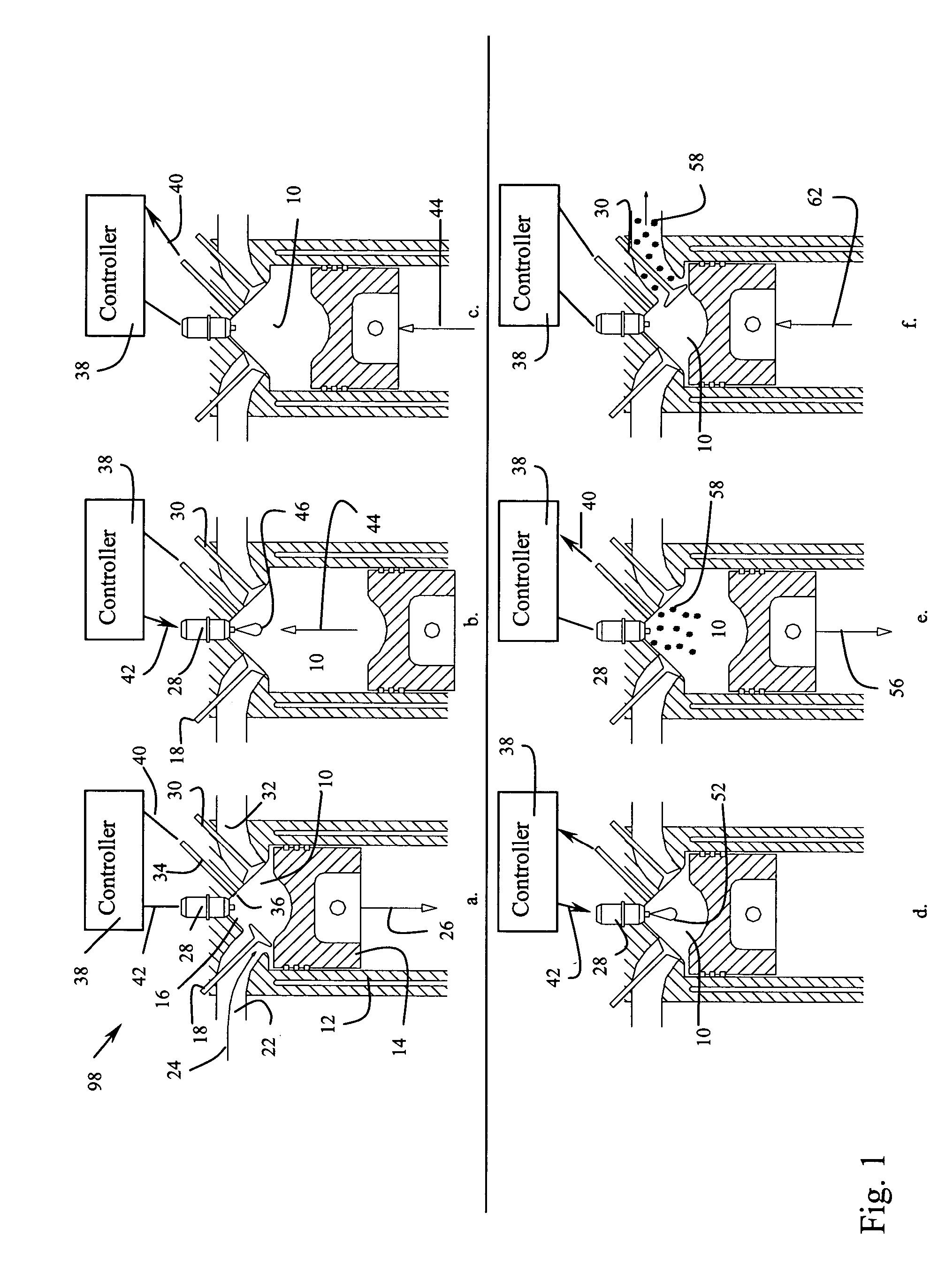
[0046]Referring to FIG. 1, a series of six figures, a through f, provide the operational strategy over the course of an engine cycle, beginning with the commencement of an intake stroke, FIG. 1a, and finishing off with the final stages of the exhaust stroke, FIG. 1f.

[0047]Specifically, referring to FIG. 1a, combustion chamber 10 of internal combustion engine 98 is defined by cylinder 12, piston 14 and fire deck 16. Piston 14 is commencing an intake stroke. Intake valve 1...


PUM


Abstract

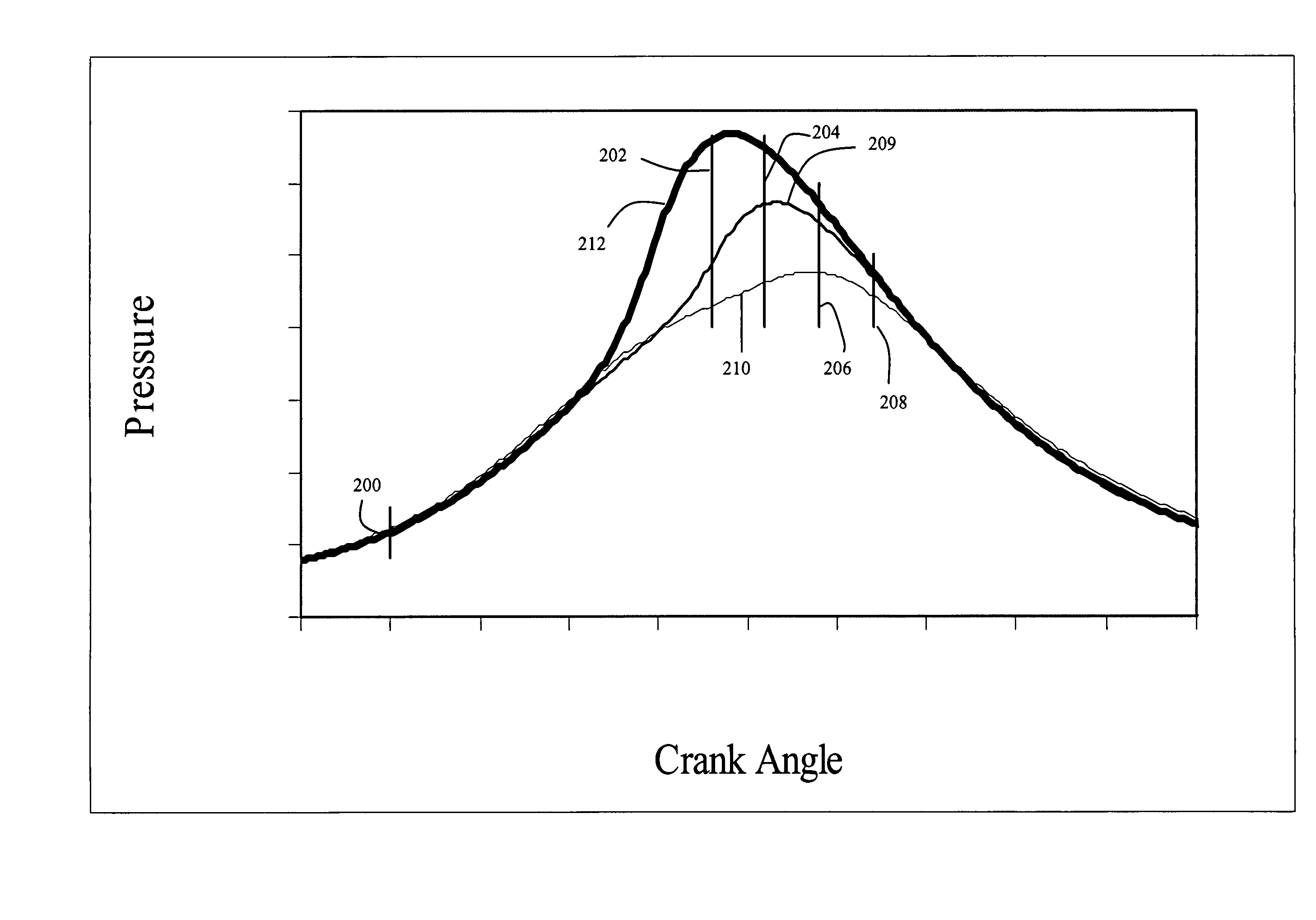
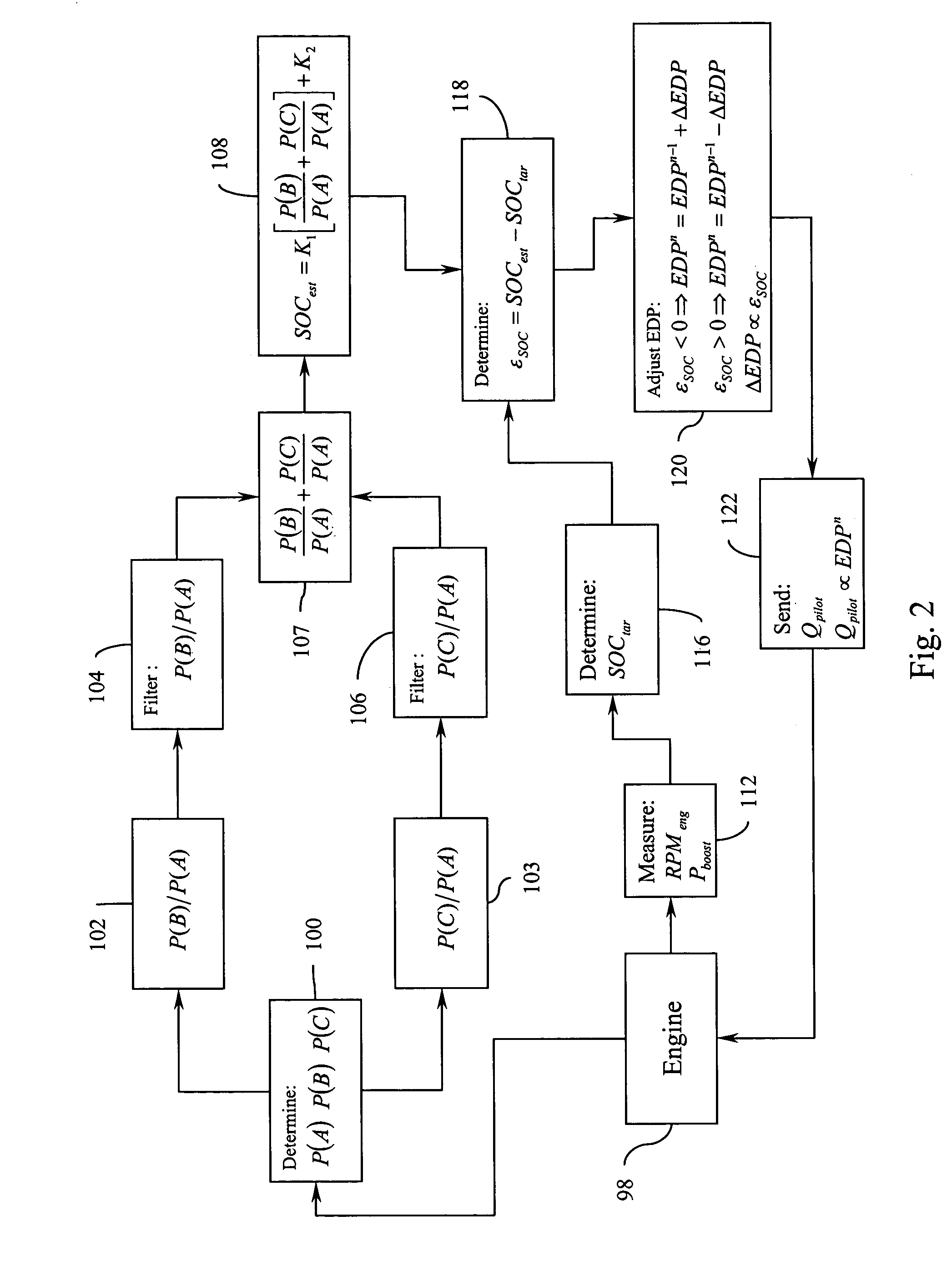
The present method and apparatus employ a signal indicative of cylinder pressure within the combustion chamber of an internal combustion engine to control combustion phasing or start of combustion (SOC) in subsequent cycles of the engine where the engine is driven by combustion of both a fuel / air premixed charge and a directly injected quantity of fuel. A ratio of signals indicative of pre-combustion pressure and post-combustion pressure within a cycle are employed to estimate SOC and then, based on a predetermined target SOC, an ignition lever is employed to adjust subsequent SOC. A preferred ignition lever is, in a pilot fuel ignited engine, pilot fuel quantity.

Description

FIELD OF THE INVENTION[0001]The present invention relates to a method and apparatus for controlling the start of combustion (or another measure indicative of combustion phasing) of an internal combustion process using sensor signals that are indicative of the pressure found in the combustion chambers of internal combustion engines. The combustion process generally involves combustion of a premixed charge of fuel and air supplemented by combustion of a directly injected quantity of fuel.BACKGROUND OF THE INVENTION[0002]Compression ignition or auto-ignition of a lean fumigated or lean premixed charge of fuel, once ignited, has the potential to burn while producing fewer pollutants such as oxides of nitrogen (NOx) and particulate matter (PM) than is the case for a non-premixed charge. Controlling ignition of such charges in an internal combustion engine can be difficult, however. Early ignition of a premixed charge during the compression stroke of the piston can result in overpressure,...

Claims


Application Information

Patent Timeline
Patent Type & Authority Patents(United States)
IPC IPC(8): F02P5/153F02B1/12F02D35/02F02D41/00F02D41/30F02P19/02
CPCF02B1/12F02D35/028F02D41/3047F02B2275/14F02D41/0025Y02T10/123F02P19/026Y02T10/128F02D41/3041Y02T10/12F02D41/04F02P5/145
Inventor ZURLOYE, AXELRUTHMANSDORFER, DAVEFRAZIER, TIMRUMSEY, JENNIFER
Owner WESTPORT POWER
Learn More