Grinding element and grinder stone

a technology of grinding element and grinding stone, which is applied in the field of grinding element, can solve the problems of insufficient fastening of the segment, insufficient sealing of the segment, and inability to manufacture, etc., and achieve the effects of improving the strength of the segment, reducing the cost of production, and improving the quality of the produ

Inactive Publication Date: 2006-02-21
VALMET TECH INC
View PDF2 Cites 10 Cited by
  • Summary
  • Abstract
  • Description
  • Claims
  • Application Information

AI Technical Summary

Benefits of technology

[0013]According to a basic idea of the invention, two or more grinding segments manufactured of grinding ceramic material are attached by means of bonding agent to the fastening frame of the grinding element in order to form a grinding surface of the element. The area of an individual grinding segment is smaller than the area of the fastening frame, wherefore several grinding segments are required to cover the outer surface of the fastening frame. The fastening frame is preferably a substantially planar element. Grinding elements formed in this manner are positioned adjacent to one another on the outer circumference of the frame of the grinder stone so as to form a desired grinding surface. Each element is fastened by one or more fastening means to the stone's frame. Since the grinding element comprises several smaller and lighter grinding segments than previously, the centrifugal force acting on an individual segment is lower than in the prior art arrangements. Furthermore, small segments are easier to manufacture than large segments, since small segments are not subjected to such high stresses as large segments during the firing of the ceramic material. Correspondingly, changes in the temperature during use, and the resulting stresses can be controlled better in small segments. Also, the area of fastening of the segments with respect to the segment's weight is greater than previously, which guarantees tight fastening of the segment. Compared to grinding segments that are fastened individually, the grinding element according to the invention can be installed in a substantially faster and easier manner. Another advantage is that a sufficiently high fastening force can be selected without a risk of damage to the ceramic segment.
[0014]Furthermore, a basic idea of a preferred embodiment of the invention is that the fastening frame of the grinding element is made of plastic. The fastening frame can also be provided with a firm fastening sleeve made of metal or the like, which is arranged in connection with a fastening hole of the grinding element and transmits the fastening force of a fastening bolt to the frame of the grinder stone. It is thus possible to select a sufficiently high fastening force without a risk of damage to the plastic frame. The plastic frame can be manufactured rapidly and at low cost for example by die-casting. The plastic fastening frame is also light and thus easy to handle during assembly. Moreover, since the fastening frame is light, it is subjected to a lower centrifugal force, which reduces the stress on the fastening means.
[0015]Yet another basic idea of a preferred embodiment of the invention is that the grinder stone is formed of at least two grinding elements. A grinding element can be made sufficiently strong for this purpose, even though the element consists of small segments. The segments according to the invention are fastened as firmly to a small grinding element as to a large grinding element. This arrangement substantially expedites the replacement of elements compared to the replacement of the previous small grinding segments.

Problems solved by technology

However, such bolts are rather complicated and therefore also expensive.
Another problem with the present arrangements is that the fastening forces subject the ceramic segment to compression stress, which can break the segment usually from below the washer.
It is thus necessary to restrict the fastening force, which in some cases can lead to insufficient fastening of the segment.
During grinding, such a loose segment starts vibrating and will be damaged.
The ceramic materials used in grinding are highly wear-resistant and hard, yet brittle.
However, in practice grinding segments cannot be manufactured from more resistant ceramic materials, since the ceramic material used in grinding of wood must be of a particular type and sufficiently porous to provide a desired grinding effect.
Yet another problem with the present grinding segments is that replacing the segments is difficult and slow.

Method used


Image

  • Grinding element and grinder stone
  • Grinding element and grinder stone
  • Grinding element and grinder stone

Examples


Embodiment Construction

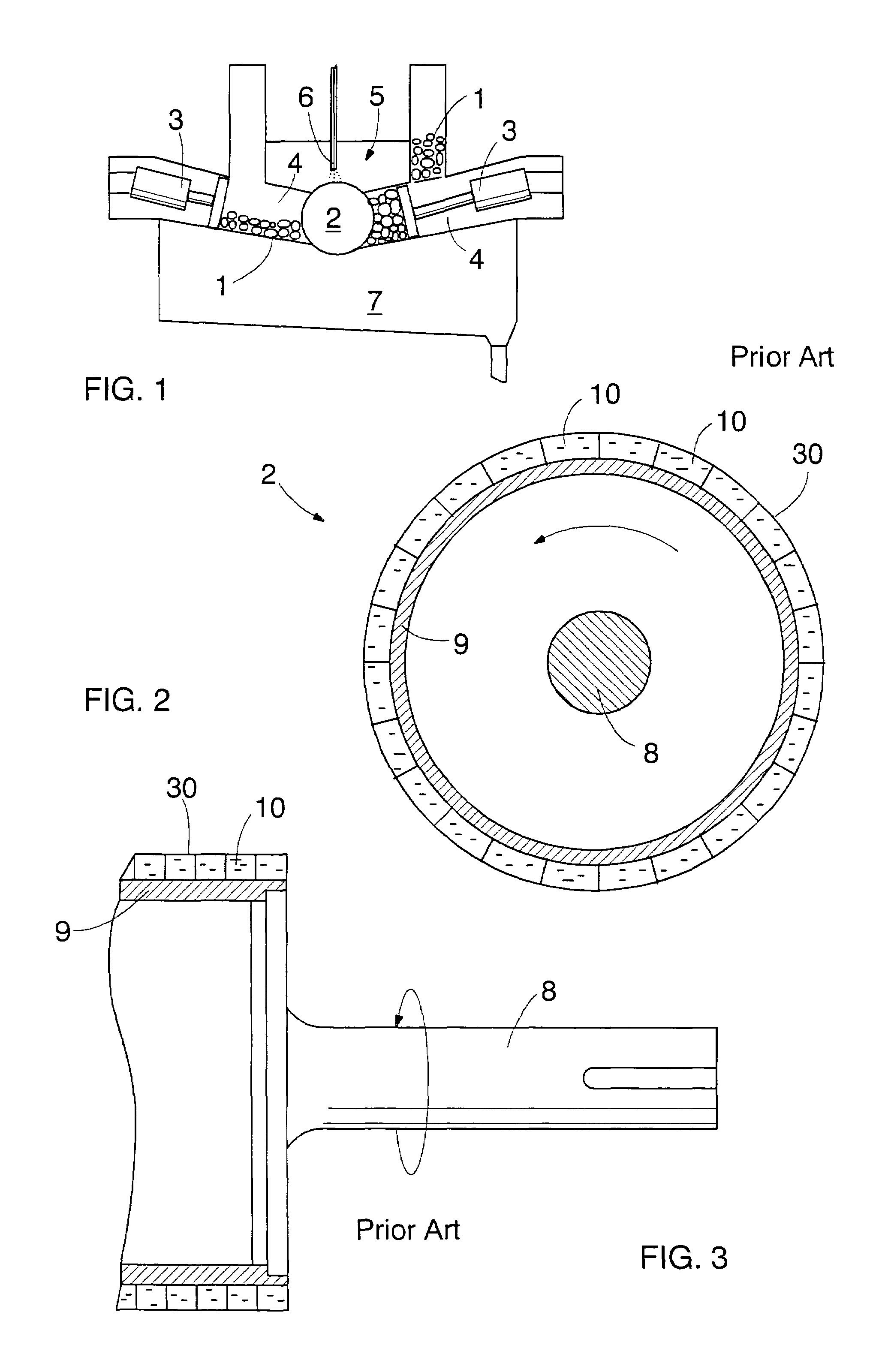
[0024]FIG. 1 shows a grinding apparatus for detaching fibers from logs 1 or some other similar wood material by means of a rotating cylindrical grinder stone 2. The logs 1 are pressed by feeder means, such as feed cylinders 3, from a feed chamber 4 against the outer surface of the grinder stone 2. Water is simultaneously supplied from nozzles 6 to a grinding chamber 5. The fiber that has been released from the logs accumulates with the sprayed water in a grinder pit 7 at the bottom of the grinding chamber and is conducted therefrom to subsequent processing steps. The grinding apparatus is considered fully known to a person skilled in the art, wherefore the structure and operation thereof do not have to be described in more detail herein.

[0025]FIG. 2 shows, in a simplified manner, a prior art grinder stone 2, which rotates around a shaft 8. The grinder stone comprises a preferably metal cylindrical frame 9, the outer circumference of which is provided with individual grinding segment...


PUM

PropertyMeasurementUnit
areaaaaaaaaaaa
forcesaaaaaaaaaa
circumferenceaaaaaaaaaa

Abstract

The invention relates to a grinding element, which comprises a substantially planar fastening frame, and where two or more grinding segments made of grinding ceramic material are fastened to the outer surface of the frame by means of bonding agent. The fastening frame preferably comprises at least one fastening hole, and a fastening bolt is supplied through the hole to fasten the grinding element to the frame of the grinder stone. The invention further relates to a grinder stone, where a grinding surface is formed by arranging a required number of grinding elements according to the invention on the outer circumference of the stone's frame.

Description

CROSS-REFERENCE TO RELATED APPLICATIONS[0001]This application is a continuation of International Patent Application PCT / FI02 / 00218 filed Mar. 15, 2002, which designated the United States and was published under PCT Article 21(2) in English, and which is hereby incorporated herein in its entirety by reference.BACKGROUND OF THE INVENTION[0002]1. Field of the Invention[0003]The invention relates to a grinding element, which can be arranged on the outer surface of a frame of a grinder stone used to defiber wood, the grinding element comprising at least one grinding segment made of grinding ceramic material, and fastening means for fastening the element.[0004]The invention further relates to a grinder stone for defibering wood, comprising a cylindrical frame, grinding segments made of grinding ceramic material and arranged on the outer circumference of the grinder stone, and a shaft, around which the grinder stone is arranged to be rotated during grinding.[0005]2. Description of Related ...

Claims


Application Information

Patent Timeline
Patent Type & Authority Patents(United States)
IPC IPC(8): B02C19/00D21B1/28
CPCD21B1/28
Inventor TUOVINEN, OLLI
Owner VALMET TECH INC
Why Eureka
Try Eureka