Polarity reversing circuit for electrostatic precipitator system

a precipitator and polarity reversing technology, applied in the direction of electrode cleaning, electric supply techniques, transportation and packaging, etc., can solve the problems of limited application, filter clogging, and limited flow through filters, so as to improve the operational effectiveness of electrostatic precipitator systems, enhance existing cleaning techniques, and reduce the time required

Inactive Publication Date: 2006-02-21
ELECTRIC POWER RES INST INC
View PDF23 Cites 26 Cited by
  • Summary
  • Abstract
  • Description
  • Claims
  • Application Information

AI Technical Summary

Benefits of technology

[0017]In a first manifestation, the invention is a method of applying electrical energy to an electrostatic precipitator collector. The method enables operationally effective cleaning using electrical energy, and enhances, supplements or eliminates the operation of mechanical rappers. According to the method, electrical energy having a first electrical polarity is applied to the electrostatic precipitator collector, and the precipitate is collected. A need for cleaning is determined, and applied electrical energy is switched from first electrical polarity to a second, opposite electrical polarity. Rapping may or may not be done while the second electrical polarity is being applied, to remove collected precipitate from the electrostatic precipitator collector. Finally, the applied electrical energy is reset to the first electrical polarity.
[0023]A first object of the invention is to improve the operational effectiveness of electrostatic precipitator systems. A second object of the invention is to reduce the time required to clean collector plates. A third object of the invention is to enhance existing cleaning techniques with a complementary and non-exclusive technique. Another object of the invention is to accomplish the foregoing using readily available electronic components. Yet another object of the invention is to facilitate better collection of fly ash from coal fueled electric utility plants.

Problems solved by technology

The techniques have heretofore been associated with certain advantages and disadvantages; hence have limited application.
Unfortunately, flow through a filter is limited by the surface area and cleanliness of the filter.
In higher volume systems, and in corrosive or extreme environments, filters tend to clog quickly and unpredictably, and present undesirable resistance to the passage of the gas stream.
During the period of filter changing or cleaning, which can be particularly tedious, the machine, equipment, or process must be stopped or diverted.
This shut-down requires either a duplicate filtration pathway, which may add substantial cost, or a shut-down of the machine or process.
Until recently, these limitations present design challenges that have primarily limited this technology to low volume purification.
Unfortunately, the liquid must also be processed; and where there are high levels of particulates, the particulates must be separated from the liquid by yet another process, or the liquid and particulates must be transported to some further industrial or commercial process or disposal location.
The added weight and difficulty of handling a liquid (in addition to the particulate) during transport makes liquid separation less desirable in many instances, particularly where there may be a demonstrated application for the particulate content within the gas stream.
Similar to washing, flocculation necessitates the introduction of additional materials that add bulk to the waste stream and unnecessarily complicate the handling and disposal of the contaminants.
Furthermore, the flocculating materials must also be provided as raw materials, which may add substantial expense in the operation of such a device, Consequently, flocculation is normally reserved for systems and operations where other techniques have been unsuccessful, or where a particular material is to be removed from the gas stream which is susceptible to specific flocculent that may provide other benefit.
However, centrifugation becomes slower and more complex as the size of the entrained particles or liquids become smaller.
Consequently, in applications such as the removal of fly ash from a combustion stream, centrifugation tends to be selective only to relatively large particles, thereby leaving an undesirably large quantity of fine fly-ash in the effluent stream.
When a sufficiently thick layer of electrically non-conductive particles has accumulated to reduce the surface potential, further significant particulate capture becomes difficult or impossible.
Consequently, and in spite of the many benefits, electrostatic precipitators have heretofore been limited in efficiency by the effects of the contaminants on the collection plates.
The rapper creates vibration in the collector electrodes, in turn causing the precipitate to drop off of the electrodes.
Unfortunately, the mechanical rapper systems of the prior art have been known to require substantial cycle times, and the mechanical forces tend to move the contaminant back into the gas stream.
Furthermore, rapper systems tend to be maintenance intensive; and, for high resistivity particulate, the rapper tends to be relatively ineffective, owing to the accumulation of electrical charge on the particulate surface.
In particular, the control system of Gallo et al illustrates the challenges of prior art systems, including many components and much complexity.

Method used


Image

  • Polarity reversing circuit for electrostatic precipitator system
  • Polarity reversing circuit for electrostatic precipitator system
  • Polarity reversing circuit for electrostatic precipitator system

Examples


Embodiment Construction

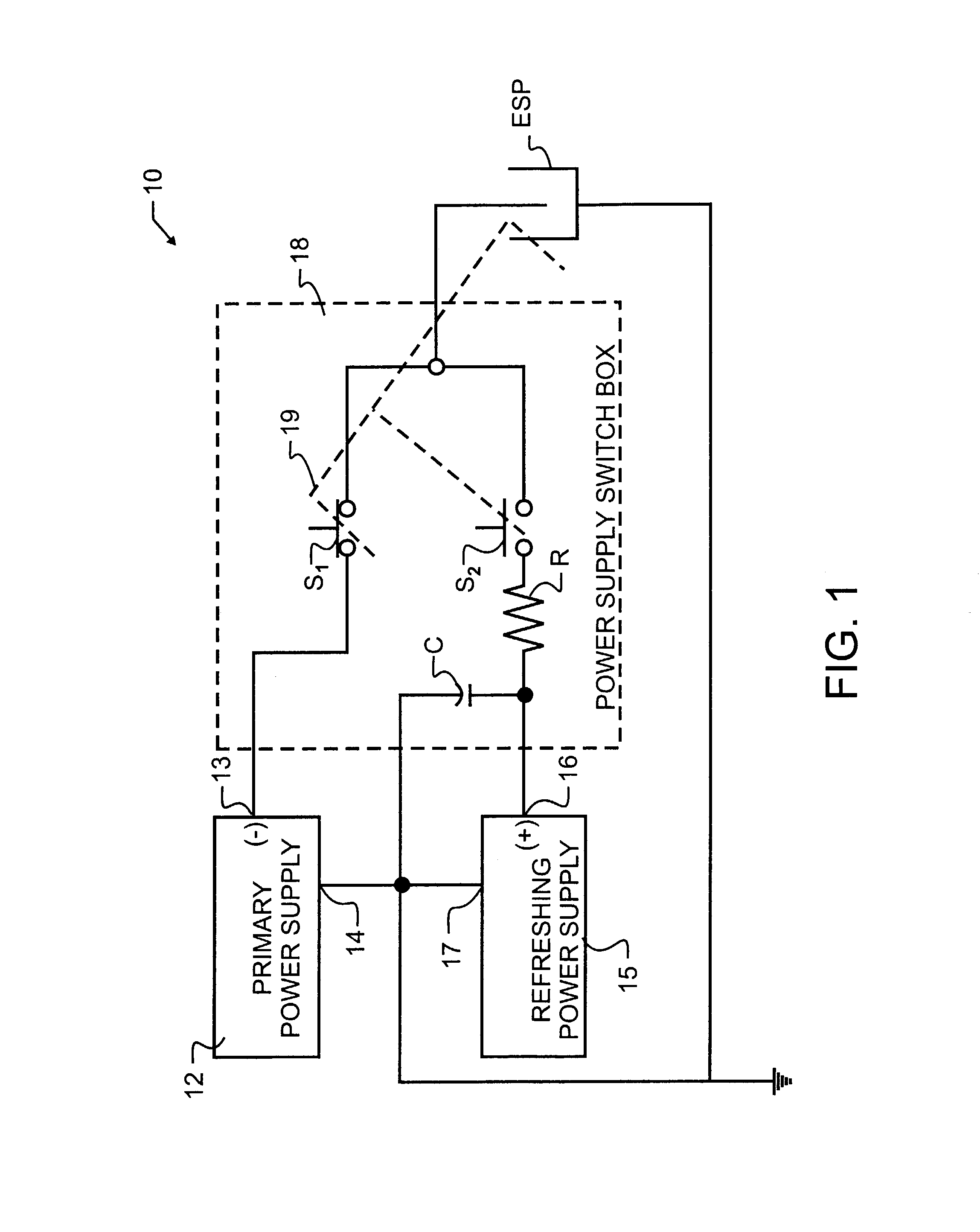
[0027]With reference to FIG. 1, a preferred polarity reversing circuit 10 includes a primary power supply 12. Power supply 12 may be of any type known in the prior art, and will typically have a first negative voltage output 13 and a second positive polarity output 14 connected to a circuit common or ground connection. In the precipitation of fly ash from an exhaust stream, using an exemplary prior art electrostatic precipitator ESP, power supply 12 will typically provide an output voltage potential of between 5 kilovolts and 150 kilovolts at an operating current typically within the range of 100 to 2500 milliamperes. The negative polarity output 13 is connected to electrostatic precipitator ESP through switch S1, which, during the standard precipitation function, remains closed.

[0028]Second refreshing power supply 15 is also preferably provided, and may preferably use the same or similar components as found in primary power supply 12. While this selection of similar components is n...


PUM


Abstract

A gas separation apparatus using electrostatic precipitators and mechanical rappers is enhanced by the addition of an opposite polarity refreshing power supply and a switching arrangement. The switching components selectively disconnect the primary power supply and connect the refreshing power supply to the electrostatic precipitator, causing an electrical impulse in the precipitator sufficient to dislodge precipitate from the collector plates. An RC filter is further provided to control the impulse and reduce the burden that would otherwise be placed upon the refreshing power supply. The novel separation apparatus and technique offer particular synergy when applied to the effluent stream from a coal-fired electric power plant or other similar gas streams.

Description

BACKGROUND OF THE INVENTION[0001]1. Field of the Invention[0002]This invention pertains generally to gas separation apparatus using an electric field. More specifically, the present invention uses non-liquid cleaning techniques to maintain electrostatic precipitator electrodes. In a most specific manifestation, a new method and apparatus are provided to dislodge ash from collection plates within an electrostatic precipitator.[0003]2. Description of the Related Art[0004]Industries as diverse as mills, pharmaceutical or chemical, food processing, and cement kilns must separate contaminants or particulates from an air or gaseous stream. The gases may be a product of combustion, such as present in an exhaust stack, but may also represent other gas streams and may contain such diverse materials as liquid particulates, smoke or dust from various sources, and the like. Separators that must process relatively large volumes of gas are common in power generating facilities and factories.[0005...

Claims


Application Information

Patent Timeline
Patent Type & Authority Patents(United States)
IPC IPC(8): B03C3/76
CPCB03C3/68B03C3/74Y10S323/903
Inventor ALTMAN, RALPH F.GUENTHER, ROBERT N.NICHOLS, GRADY B.
Owner ELECTRIC POWER RES INST INC
Why Eureka
Try Eureka