Highway vehicular traffic flow control

a technology for vehicular traffic and highways, applied in traffic control systems, position/direction control, analog and hybrid computing, etc., can solve the problems of inability to absorb extant traffic volume pressure, multiple vehicle collisions on the carriageway, and slow down, and achieve the effect of increasing the overall flow of traffi

Inactive Publication Date: 2006-02-21
LAWRENCE MALCOLM G
View PDF10 Cites 100 Cited by
  • Summary
  • Abstract
  • Description
  • Claims
  • Application Information

AI Technical Summary

Benefits of technology

[0033]In high traffic load conditions for any particular lane, traffic redistribution over plural lanes may be desirable either to increase overall flow of traffic or to enable satisfaction of individual vehicle speed aspirations whilst not deleteriously affecting overall flow rate. In the latter case, it is desirable to cause redistribution out of fast lines. In such cases, redistribution can be accomplished by signals demanding lane change. Usually, such signals should be directed to selected vehicles rather than randomly. Selectivity may be on the basis of absolute position in the capsule concerned. For example, vehicles relatively forward in the capsule ...

Problems solved by technology

The availability of choice to vehicle drivers engenders a number of serious problems which in many cases are as apposite to increasing highway inefficiency as the increasing numbers of vehicles licensed to use the highways.
UK motorways (and the broadly similar roads referred to by local nomenclature in other countries) and other principle traffic routes experience a number of sometimes remarkable problems engendered by exercise of choice by vehicle drivers.
Slowing can be catastrophic causing multiple vehicle collisions in the carriageway experiencing slow-down.
As driver alertness and vehicles distances vary from one driver/vehicle to another, the highway will inevitably experience the comparatively precipitous deceleration of one or more vehicles, and this produces a tail-back envelope of similarly precipitously decelerating vehicles many of which will decelerate to a speed substantially slower than the lead vehicles with some coming to a standstill.
Slow speed conditions of the highway may render it incapable of absorbing extant traffic volume pressures, highway capsules in the tail emanating from the lead vehicles being forced to stasis as they cannot be admitted to more forward parts of the highway.
However, tests show that multiple lane changing achieves little for the vehic...

Method used


Image

  • Highway vehicular traffic flow control
  • Highway vehicular traffic flow control

Examples


example 1

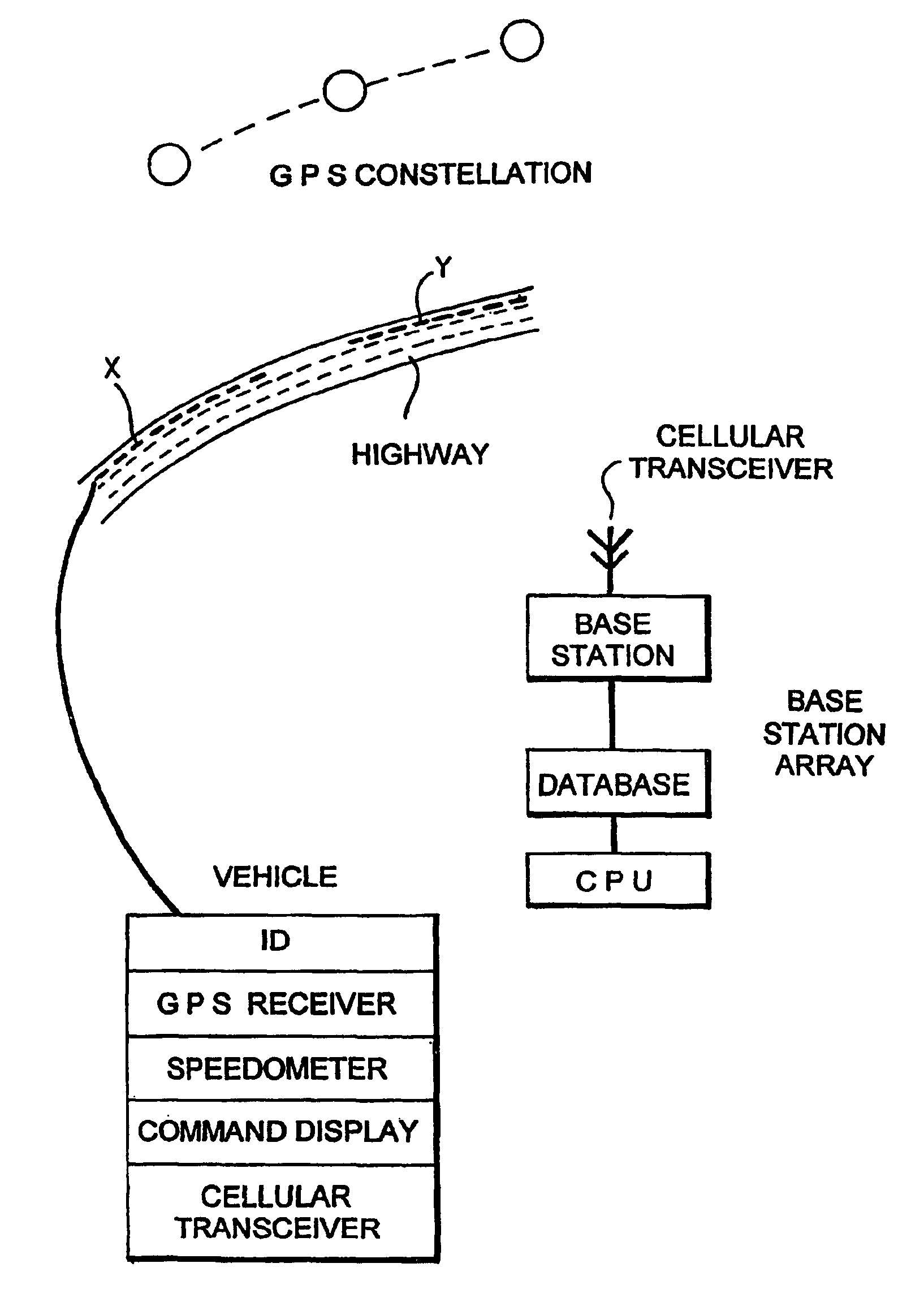
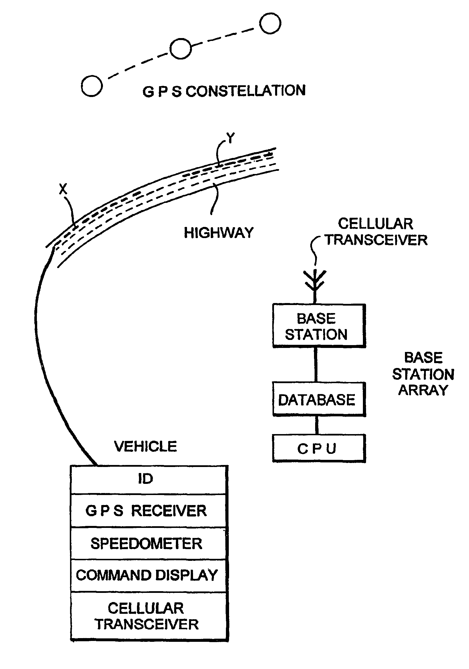
[0038]A capsule A of vehicles comprising twenty five cars of various sizes and types is advancing along a lane of a three-lane carriageway at a speed of 59 mph. The capsule is lead by a car C1 (having a speed of 59 mph). The capsule occupies the outside lane of the carriageway. Beyond the head of the capsule is the tail car C2 of a further capsule B advancing at a speed of 64 mph. Car C1 has signalled its position, speed and essential ID (including type and registration details) to a base station as has car C2 and the other cars in the capsule and the base station has determined the required vehicle module lengths and the excess space if any between the vehicles in the capsule at the respective vehicle speeds. The base station has further determined that the capsule A is lagging the capsule B by 0.6 miles.

[0039]The base station signals car C1 to display a command to increase speed to a limit, which will be 70 mph in the case of UK highway law, or to pull over to the centre lane. Car...

example 2

[0040]A capsule A1 of vehicles has the composition of capsule A in Example 1 except that one of the vehicles is a truck T12 positioned at position 12 in the capsule.

[0041]The capsule is advancing in the outside lane of a three-lane carriageway at a speed of 53 mph. Capsule B advances away from the head vehicle in capsule A1 at a speed of 64 mph. The instantaneous lag of capsule A1 to the rear of capsule B is 0.6 miles.

[0042]The lead vehicle A1 in capsule A1 is signalled by the base station to increase speed to a limit equal to the approximate maximum for cars on dual-carriageway roads (eg 70 mph) or to pull over. Once it has done either, the base station is programmed successively to signal the following vehicles capable of the limit speed to do the same, transmitting such signals in response to a trigger operating when the distance between a signalled vehicle and the next in sequence along the travel path of the latter reaches a predetermined threshold or when the signalled vehicle...

example 3

[0043]Two traffic capsules A and B are travelling on a highway as noted in Example 1 but there are also Capsules C to J ahead of Capsule B forming a total of five pairs of capsules all related to one another as are Capsules A and B in Example 1 and each capsule pair being spaced from the next by 0.7 miles. The capsules travel in the outer lane of the southbound carriageway of the highway. In the northbound carriageway, an accident has occurred and the traffic there is in stasis. As Capsule J approaches the virtual constriction represented by the stationary traffic in the northbound carriageway, slow-down will ordinarily begin to occur as the accident spectacle is observed by a portion of the drivers in the outer lane of the southbound carriageway. The stasis in the northbound carriageway has, however, been recognised by the base station as a result of signals received thereby (eg from slow vehicles in that carriageway). Its response is to reconfigure the virtual models for the Capsu...


PUM


Abstract

A base station receives signals from highway traffic and sends signals to selected vehicles on the highway to command them to increase/decrease speed or charge lane in order to more closely conform to a virtual model for vehicular use of the highway.

Description

FIELD OF THE INVENTION[0001]The invention relates to road traffic flow control and in particular to a method of road traffic flow control in which real traffic flow is monitored and in which, by signalling individual vehicles with attitude change instructions (affecting vehicle model highway use characteristics) which in aggregate theoretically conform real traffic flow to a computer virtual model representing a flow conforming to an ideal, real flow is adapted as an emulation of the virtual model flow.BACKGROUND OF THE INVENTION[0002]A highway transmits vehicular traffic as plural discrete (but often almost contiguous) advancing highway traffic capsules each of which comprises plural vehicles which remain relatively static within the respective advancing traffic capsules as the latter are transmitted along the highway. Efficient advancement of a highway traffic capsule, in the sense of maximum safe vehicle volume passage per unit time, requires a balance between vehicle count in th...

Claims


Application Information

Patent Timeline
IPC IPC(8): G08G1/123G08G1/01G08G1/0967
CPCG08G1/01G08G1/096725G08G1/22G08G1/096775G08G1/09675
Inventor LAWRENCE, MALCOLM G.
Owner LAWRENCE MALCOLM G
Why Eureka
Try Eureka