Integrated power and cooling architecture

a technology of power and cooling architecture and integrated structure, which is applied in the direction of power cables, cables, electrical apparatus casings/cabinets/drawers, etc., can solve the problems of high cost, high cost, and high cost of components, and achieves a smaller packaging envelope, increased output power, and high reliability operation.

Inactive Publication Date: 2006-02-21
LOCKHEED MARTIN CORP
View PDF46 Cites 38 Cited by
  • Summary
  • Abstract
  • Description
  • Claims
  • Application Information

AI Technical Summary

Benefits of technology

[0007]The present invention is directed to thermal management structures and energy storage components that can allow for increased output power and higher reliability operation without increasing the prime or point-of-load power source and can contribute to miniaturization and smaller packaging envelopes.

Problems solved by technology

Electronics, such as radio frequency (RF) transmit / receive electronics, can be relatively inefficient, e.g., 15–25% at converting electrical energy to radiated power and therefore generate large amounts of heat.
The electronics often do not have sufficient thermal mass to absorb this waste heat with consequential rapid junction rise and component failure.
Traditional thermal management solutions to address this problem can add significant volume and complexity and can limit device miniaturization.
In addition, RF power amplifiers, such as those found in cellular telephones, web-enabled communication and personal data assistant (PDA) devices, and wireless broadband data link systems, can incur voltage droop during transmission.
Voltage droop can become more difficult to minimize as the RF power increases.
However, with higher power RF power amplifiers, the overall volume and weight increase when using existing capacitor technologies.
In certain instances, there is insufficient volume to package these traditional capacitor technologies to provide adequate RF performance at higher power levels.

Method used


Image

  • Integrated power and cooling architecture
  • Integrated power and cooling architecture
  • Integrated power and cooling architecture

Examples


Embodiment Construction

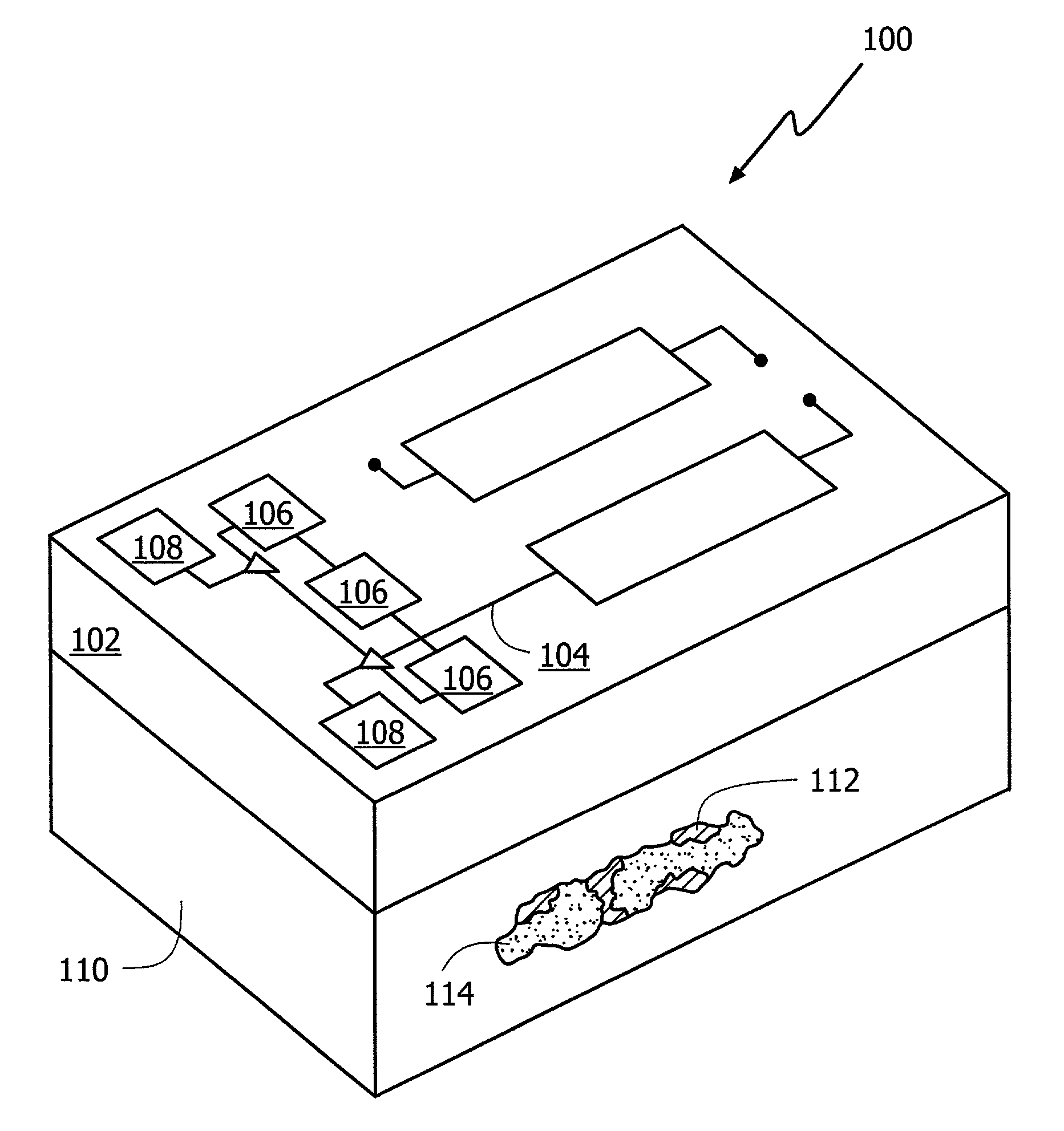
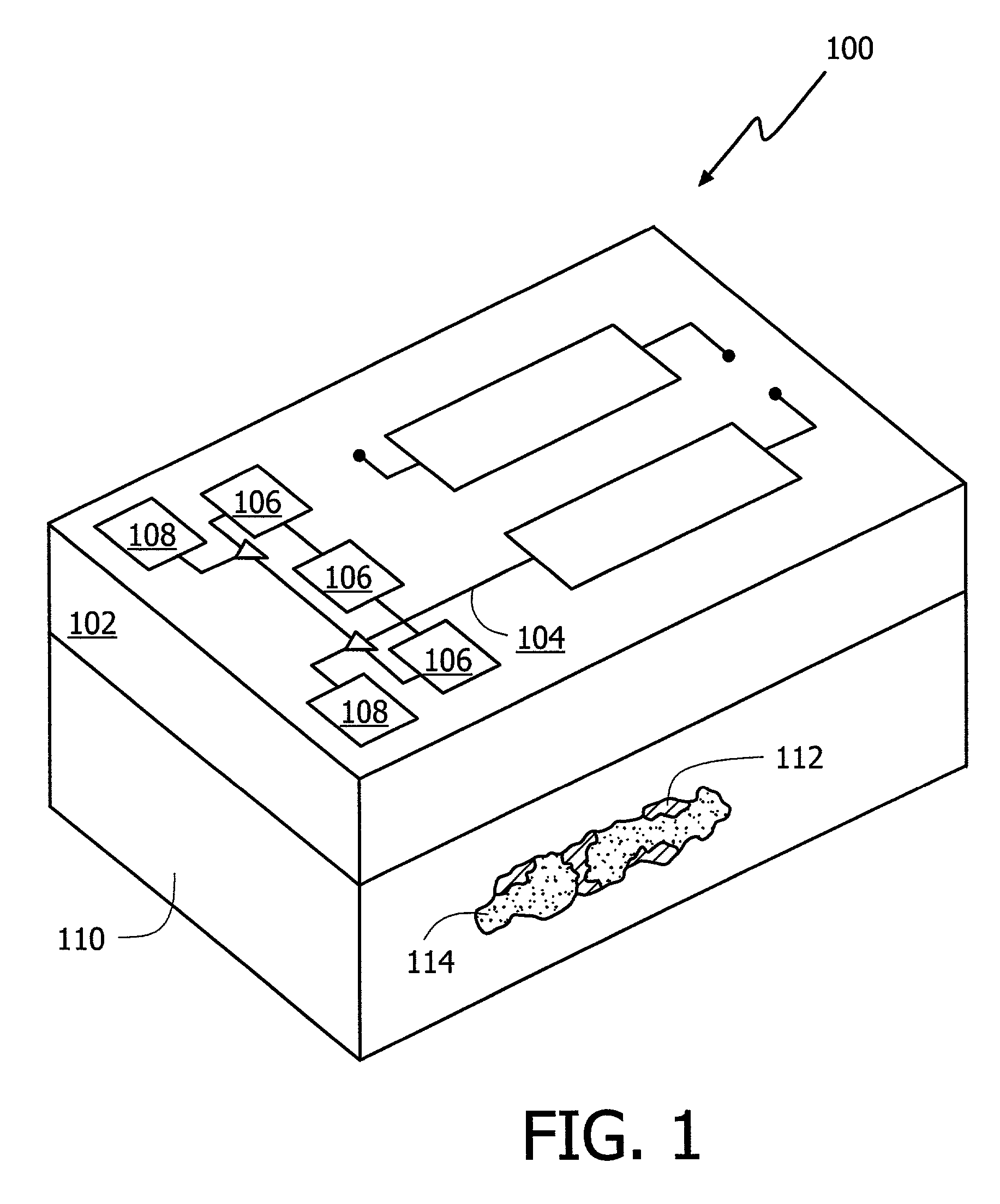
[0025]An exemplary integrated power and cooling apparatus for electronics is illustrated in FIG. 1 as an apparatus 100. The FIG. 1 apparatus 100 includes a substrate 102 having an electrical conductor 104, an energy storage device 106 mounted on the substrate 102, an electrical load 108 mounted on the substrate 102 in electrical communication with the energy storage device 106, and a thermal management structure 110 abutting the substrate 102. The thermal management structure 110 has a structural support 112 and a phase change material 114 integrated into a void space of the structural support 112. The thermal management structure 110 is in thermal communication with at least a portion of a heat producing section of the electrical load 108.

[0026]The apparatus has a substrate represented by substrate 102. In exemplary embodiments, the substrate is a composite-based or metallic-based structure. For example, the substrate can be graphite or silicon-carbide-aluminum (SiC / Al) based. The ...


PUM


Abstract

An integrated thermal apparatus for improved electronic device performance has an energy storage device coupled with a thermoelectric management device for managing thermal energy generated by the electronic device. The thermoelectric management device can include a semiconductor thermoelectric device and phase change material, which can be integrated into a foam aluminum structure. The energy storage device can be a nanometallic device. The electrical load electrical efficiency is improved by co-locating it with thermoelectric management device directly on a composite substrate foundation to provide enhanced waste heat conversion to electrical energy. The apparatus manages the thermal and power issues at the substrate level in close proximity to the electrical load and incorporates the needed thermal mass into the support structure by way of a phase change material.

Description

[0001]This application claims priority under 35 U.S.C. § 119(e) to U.S. Provisional Application No. 60 / 350,924 entitled INTEGRATED POWER AND COOLING ARCHITECTURE and filed on Jan. 25, 2002, the entire content of which is hereby incorporated by reference.BACKGROUND[0002]1. Field of Invention[0003]The present apparatus relates generally to integrated thermal management structures and energy storage components. More specifically, the apparatus relates to an integrated architecture that provides electrical power and cooling to an on-structure electrical load.[0004]2. Background Information[0005]Electronics, such as radio frequency (RF) transmit / receive electronics, can be relatively inefficient, e.g., 15–25% at converting electrical energy to radiated power and therefore generate large amounts of heat. The electronics often do not have sufficient thermal mass to absorb this waste heat with consequential rapid junction rise and component failure. Traditional thermal management solutions ...

Claims


Application Information

Patent Timeline
Patent Type & Authority Patents(United States)
IPC IPC(8): H05K7/20H01L23/373H01L23/427H01L35/00
CPCH01L23/3733H01L23/427H01L35/00H01L2924/3011H01L2924/0002H01L2924/00H10N10/00
Inventor ELIAS, J. MICHAELCEPAS, BRUCE M.KORN, JAMES A.
Owner LOCKHEED MARTIN CORP
Why Eureka
Try Eureka