Steam turbine, steam turbine plant and method of operating a steam turbine in a steam turbine plant

a technology of steam turbine and steam turbine plant, which is applied in the direction of liquid fuel engines, separation processes, liquid degasification, etc., can solve the problems of weakening the inability to effectively operate, and the inability to solve problems, so as to improve the thermal efficiency of the plant, maintain the strength of the turbine constituent components, and increase the temperature of reheated steam

Active Publication Date: 2006-02-28
KK TOSHIBA
View PDF15 Cites 26 Cited by
  • Summary
  • Abstract
  • Description
  • Claims
  • Application Information

AI Technical Summary

Benefits of technology

[0010]Accordingly, an advantage of an aspect of the present invention is to provide a steam turbine, steam turbine plant and method of operating a steam turbine in a steam turbine plant that improves the plant the

Problems solved by technology

However, such a system cannot effectively operate with a temperature of the reheated steam above about 1300 degrees Fahrenheit (or about 700 degrees Celsius), and there remain problems to be solved.
With such temperature, the constituent components exposed to such high temperature may cause steam oxid

Method used


Image

  • Steam turbine, steam turbine plant and method of operating a steam turbine in a steam turbine plant
  • Steam turbine, steam turbine plant and method of operating a steam turbine in a steam turbine plant
  • Steam turbine, steam turbine plant and method of operating a steam turbine in a steam turbine plant

Examples


Embodiment Construction

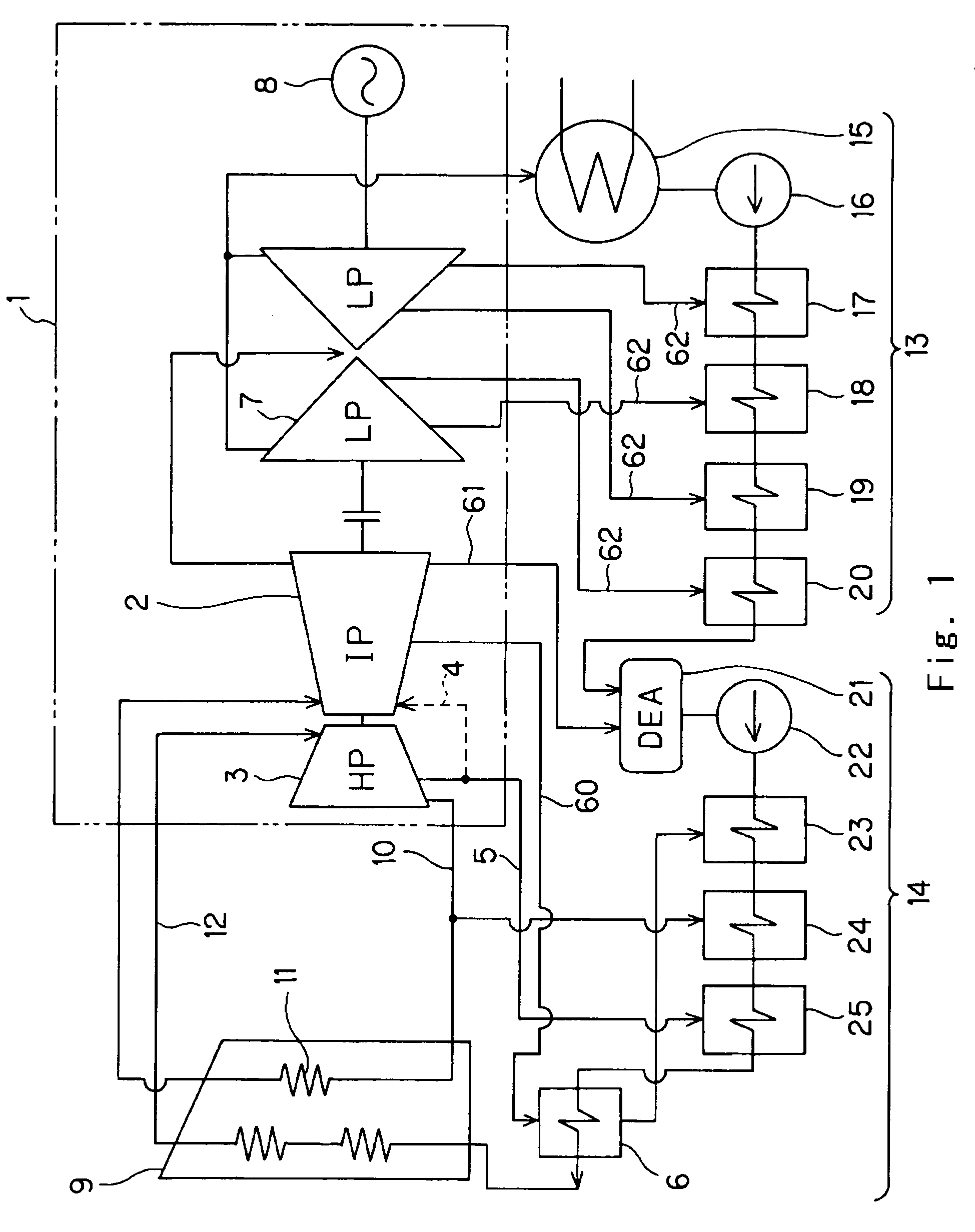
[0019]An embodiment in accordance with the present invention will be explained with reference to FIGS. 1 to 4. FIG. 1 is a schematic diagram showing an embodiment of a steam turbine plant according to the present invention.

[0020]A steam turbine plant includes a steam turbine 1, a boiler 9 as a steam generator, a condensate system 13 and a feedwater system 14.

[0021]Steam turbine 1 includes an intermediate pressure turbine 2, a high pressure turbine 3, a low pressure turbine 7 having a double-flow type configuration and a generator 8. Rotating shafts of those intermediate pressure turbine 2, high pressure turbine 3, low pressure turbine 7 and generator 8 are connected each other, steam turbine 1 has a one rotating shaft as a whole.

[0022]Boiler 9, as a steam generator, produces high pressure main steam, which is supplied to high pressure turbine 3 through line 12. The main steam expands while it flows through the high pressure turbine 3, performing expansion work that drives high press...


PUM

PropertyMeasurementUnit
Temperatureaaaaaaaaaa
Angleaaaaaaaaaa
Pressureaaaaaaaaaa

Abstract

A steam turbine and steam turbine plant that can utilize a relatively higher reheated steam, such as about 1300 degrees Fahrenheit or higher, is provided. A steam turbine plant includes a steam generator generating high pressure steam and reheated steam, a high pressure turbine driven by the high pressure steam generated by the steam generator, and an intermediate pressure turbine driven by the reheated steam. A steam bleed line coupled with the high pressure turbine bleeds steam from the high pressure turbine as cooling steam. The intermediate pressure turbine includes a heated steam inlet for receiving the reheated steam, and a cooling steam inlet for receiving the cooling steam. The cooling steam cools components of the intermediate pressure turbine that receive the reheated steam. A low pressure turbine is driven by steam discharged from the intermediate pressure turbine, and a condenser condenses steam discharged from the low pressure turbine into water as a condensate. A plurality of feedwater heaters heat the condensate to produce feedwater provided to the steam generator.

Description

CROSS REFERENCE TO RELATED APPLICATION[0001]This application is based upon and claims the benefit of priority from the prior Japanese Patent Application No. 2003-125672 filed on Apr. 30, 2003, the entire contents of which are incorporated herein by reference.[0002]1. Field of the Invention[0003]This invention relates to a steam turbine, a steam turbine plant and a method of operating a steam turbine, and in particular a turbine, turbine plant and method that permits operation with an increased steam temperature.[0004]2. Description of the Background[0005]Recently, for steam turbine plants, increasing the temperature of steam has been discussed to improve the thermal efficiencies of plants.[0006]Conventional steam turbine plants generally introduce a one-stage reheating configuration using reheated steam. In the steam turbine plant with the one-stage reheating configuration, steam at a temperature of about 1000 degrees Fahrenheit is used for a high pressure turbine, while steam at a ...

Claims


Application Information

Patent Timeline
IPC IPC(8): F01K13/02F01D25/12F01K13/00
CPCF01K13/006F01D25/12B22F2998/10F05D2260/2322
Inventor YAMASHITA, KATSUYANAGANE, KOHEISHINOZAKI, YUKIO
Owner KK TOSHIBA
Why Eureka
Try Eureka