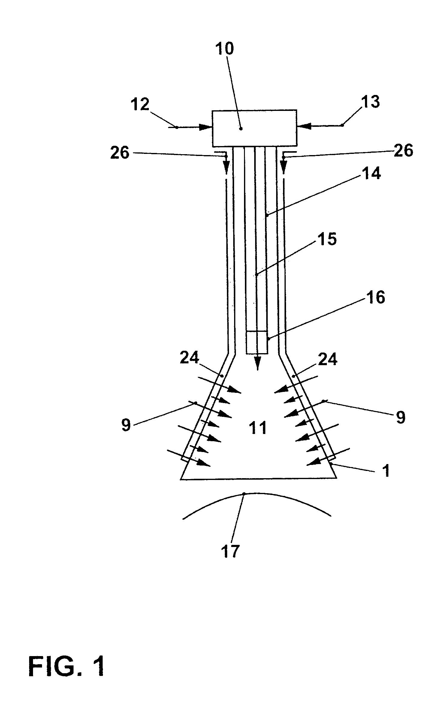
[0015]The geometry of the swirl generator, and also of an optional swirl space, can be selected in various ways in the present burner, and in particular may have the geometries which are known from the prior art. The fact that the first fuel outlet openings are distributed exclusively at the combustion chamber-side end of the burner or swirl space, around the burner axis, reliably prevents flashback of the synthesis gas. Mixing with the combustion air emerging from the burner is nevertheless ensured. Synthesis gas with a high
hydrogen content (45% by volume) can be burnt in undiluted form (LHV=14,000 kJ / kg). The burner therefore allows safe and stable combustion both of undiluted synthesis gas and of dilute synthesis gas. This ensures a high degree of flexibility when using a gas
turbine equipped with burners according to the invention in an IGCC process. By using a configuration of the first fuel feed with a correspondingly adapted cross-section, it is possible to safely pass high volumetric flows, up to a factor of 7 compared to the supply of
natural gas in known burners from the prior art, to the location of injection at the burner outlet.
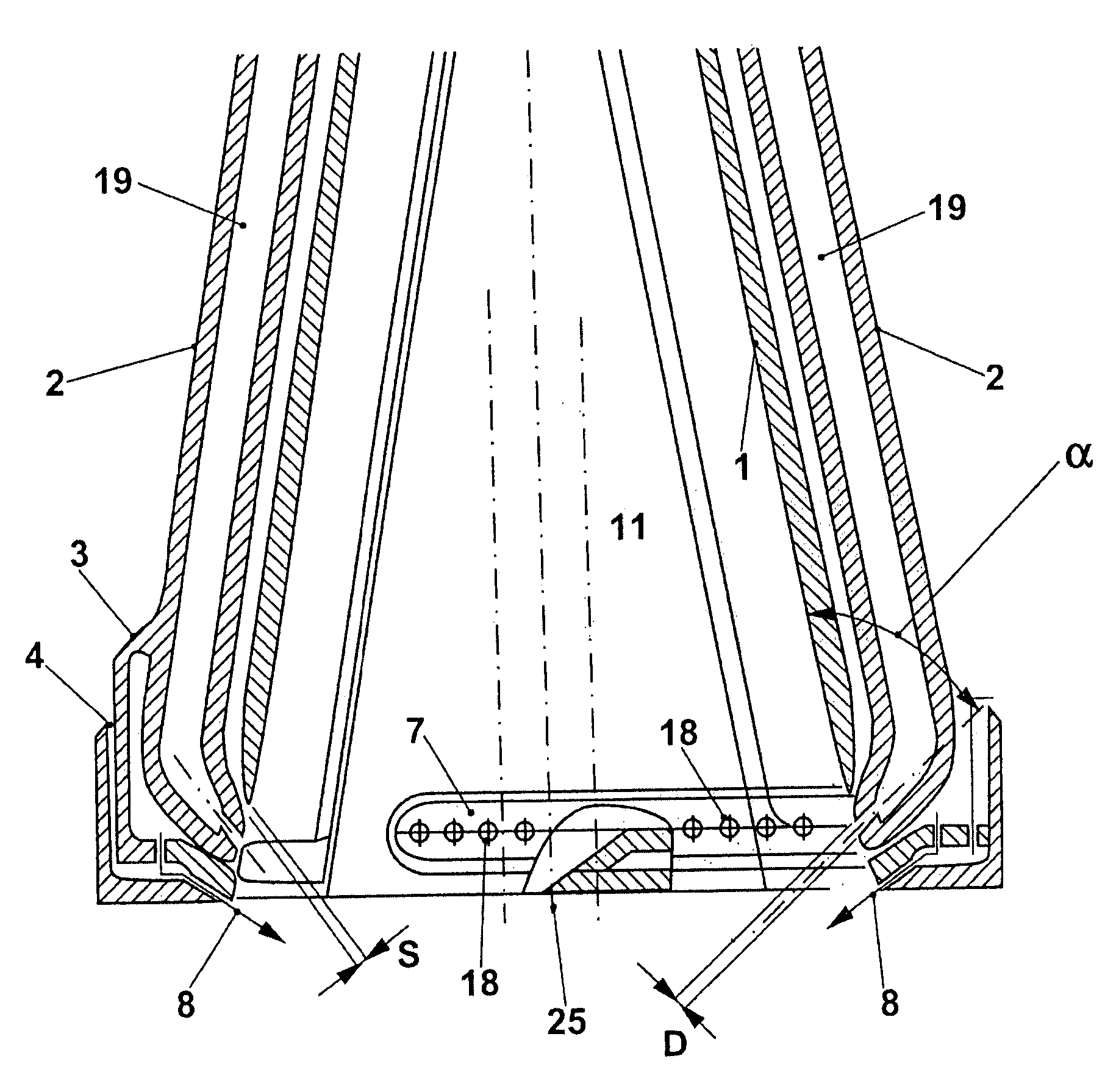
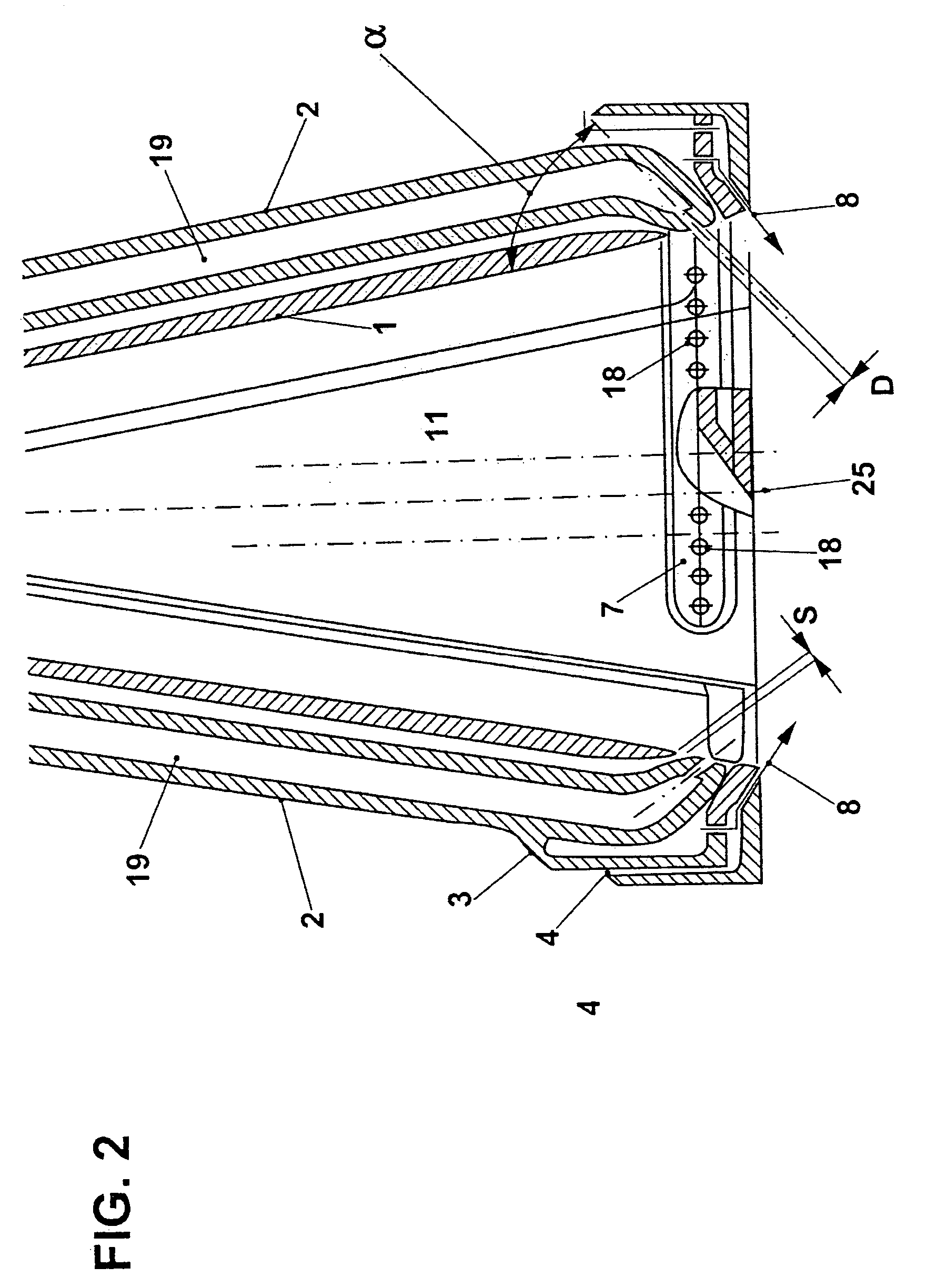
[0016]In the case of the present burner, the one or more first fuel feeds with the associated first fuel outlet openings are mechanically and thermally decoupled from the swirl generator or the burner shells which form the swirl generator and are significantly warmer in operation. As a result, the thermal stresses between the relatively cold first fuel feeds, also referred to below as gas passages, and the warmer burner shells are avoided or at least greatly reduced. For example, in one embodiment of the present invention, as is explained in more detail in the exemplary embodiments, the injection area for the synthesis gas in the burner shells is completely
cut out. The first gas passage is directly anchored in this cutout of the burner shells. As a result, gas passage and burner shells are thermally and mechanically decoupled from one another, and the design problem at the connecting locations between cold gas passage and warm burner shell is resolved. Earlier designs, such as those shown in EP 0 610 722 A1, had problems particularly with regard to the connection of relatively cold gas passage to hot burner shell, for example had cracked resulting from the
high concentration of stresses at these connecting locations. The required service life of the burner is achieved by the decoupled solution and the proposed design.
[0017]The decoupling of individual fuel lances from the burner shells is already known from EP 1 070 915. In the present burner, however, this mechanical decoupling is for the first time realized using integral gas passages with circumferentially homogeneous introduction of gas. Compared to the injection of gas which is known from EP 1 070 950, the circumferentially homogeneous injection of gas in accordance with the invention has benefits in terms of achieving a significantly more uniform distribution of the fuel in the combustion air, and therefore, in particular when using Lbtu and Mbtu fuels, improved emission levels combined, at the same time, with a good
flame stability. There is no need for complex
specific heat insulation for the gas passage with respect to the hot burner shell, for example by means of the known gas passage inserts.
[0019]The preferred design of the present burner with one or more further fuel feeds results in a multifunctional burner which safely and stably burns a very wide range of fuels. The burner in particular ensures the stable and safe combustion of Mbtu synthesis gases with calorific values (net calorific value NCV or lower heating value LHV) of 3500–18,000 kJ / kg, in particular 6000 to 15,000 kJ / kg, preferably of 6500 to 14,500 kJ / kg or from 7000 to 14,000 kg / kJ. In addition to the safe and stable combustion of undiluted and dilute synthesis gas, it is also possible to use
liquid fuel, for example diesel oil, as back-up fuel. In this case, the calorific value of the fuels used may differ significantly, for example in the case of diesel oil a calorific value LHV=42,000 kJ / kg, and in the case of synthesis gas a calorific value of 3500–18,000 kJ / kg, in particular 6000 to 15,000 kJ / kg, preferably from 6500 to 14,500 kJ / kg or from 7000 to 14,000 kg / kJ.
[0023]In the case of oil being used as fuel, the design which is known from the prior art, with the oil or oil-water
emulsion being injected via the burner lance, is retained.
Gas turbines which burn synthesis gas have to ensure mixed operation of ignition fuel and synthesis gas by using different boundary conditions, such as incorporation of the gas
turbine in the IGCC process or fixed burner groupings that are to be retained. The burner described here functions stably and safely even in mixed operation using diesel oil and synthesis gas in various mixing ratios. It can be safely operated in mixed operation for prolonged periods of time. Therefore, the gas
turbine achieves further flexibility and in operation can change from one fuel to the other. The possibility of mixed operation represents a significant operating
advantage.

