
Hybrid spinner for making a mixture of single-glass and dual-glass fibres right at the fibre forming stage

a hybrid spinner and fibre forming technology, which is applied in the direction of yarns, lighting and heating apparatus, furnace types, etc., can solve the problems of not being able to make an insulation product that is suitable for the geometry of virtual straight fibres offered by a conventional rotary fiberizing process is not the best one for forming some high-performance thermal and acoustic insulation products, and the method is not practical for making insulation products. achieve the effect o

Inactive Publication Date: 2006-02-28
OTTAWA FIBER
View PDF23 Cites 9 Cited by
  • Summary
  • Abstract
  • Description
  • Claims
  • Application Information

AI Technical Summary

Benefits of technology

"The present invention provides an integrated or hybrid dual-glass / single-glass spinner and a method to produce a mixed straight / curly fibre insulation product with improved thermal and mechanical properties. The spinner has a unique design with alternating layers of glass A and B along the inner surface of the spinner peripheral wall, resulting in a high density exit hole pattern with the required distribution of single-glass and dual-glass orifices on the peripheral wall surface. The spinner can be used with or without a separate baffle casting, and the orifice configurations can be modified to produce different types of fibers. The invention also includes an apparatus for making bi-component glass fibers with single straight and dual-glass components. The technical effects of the invention include improved thermal and mechanical properties, reduced compression ratio, and improved insulation with straight and curly fibers."

Problems solved by technology

It has been recognized that virtually straight fibre geometry, offered by a conventional rotary fiberizing process, certainly is not the best one for forming some high performance thermal and acoustical insulation product.
Both the fibre and process were not suitable for insulation products.
Some other patents disclosing methods of making curly or kinky glas fibres are disclosed in U.S. Pat. Nos. 3,236,616 and 4,145,199, but sill these methods would not be that practical for making an insulation product.
It is generally accepted that a non-rotary fibre-forming process cannot effectively compete with the rotary one for the economic manufacture of a typical glass fibre-insulating product.
The issues are a substantially lower throughput capacity and too coarse fibre to make a good glass wool.
As a consequence, some methods of imparting kink by pulling fibre from a textile bushing and mechanically crimping it by passing fibre, while still in a hot state, through a series of opposed intermeshing gears are not a viable option.
Clearly, a throughput capacity offered by these dual-glass spinners cannot be reasonably high, making the whole operation rather costly.

Method used


Image

  • Hybrid spinner for making a mixture of single-glass and dual-glass fibres right at the fibre forming stage
  • Hybrid spinner for making a mixture of single-glass and dual-glass fibres right at the fibre forming stage
  • Hybrid spinner for making a mixture of single-glass and dual-glass fibres right at the fibre forming stage

Examples


Embodiment Construction

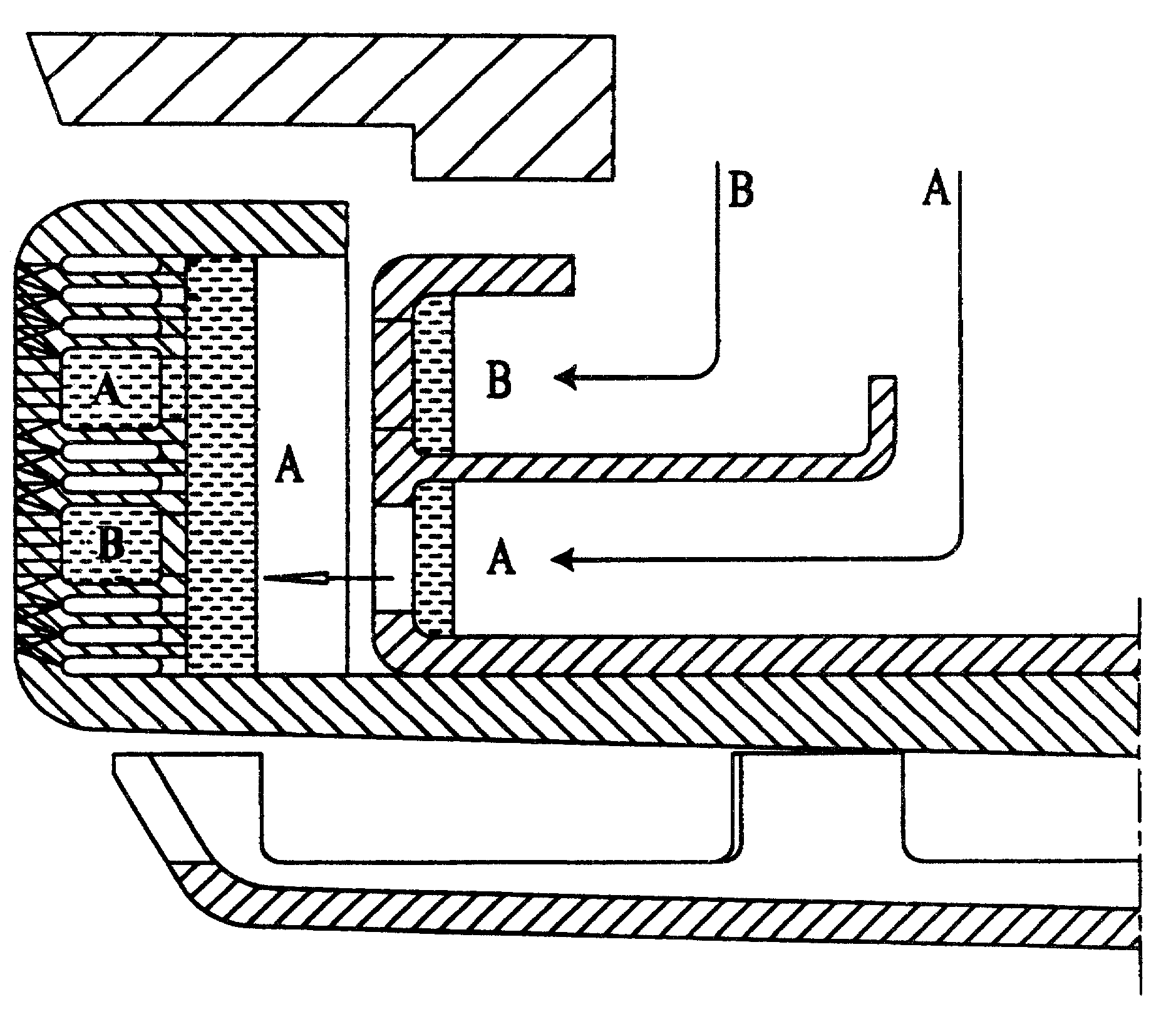
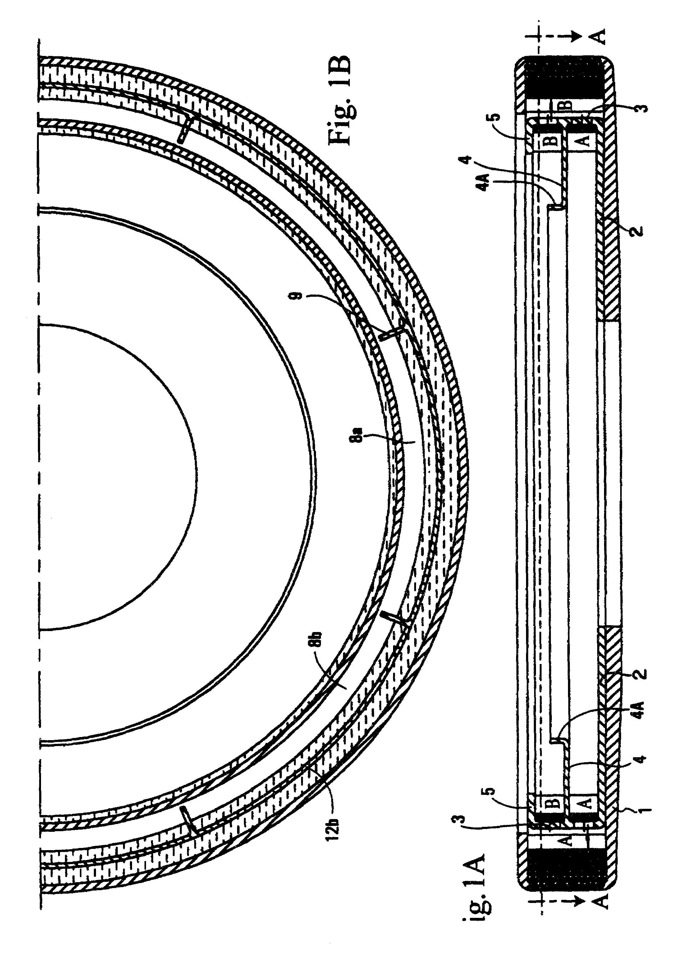
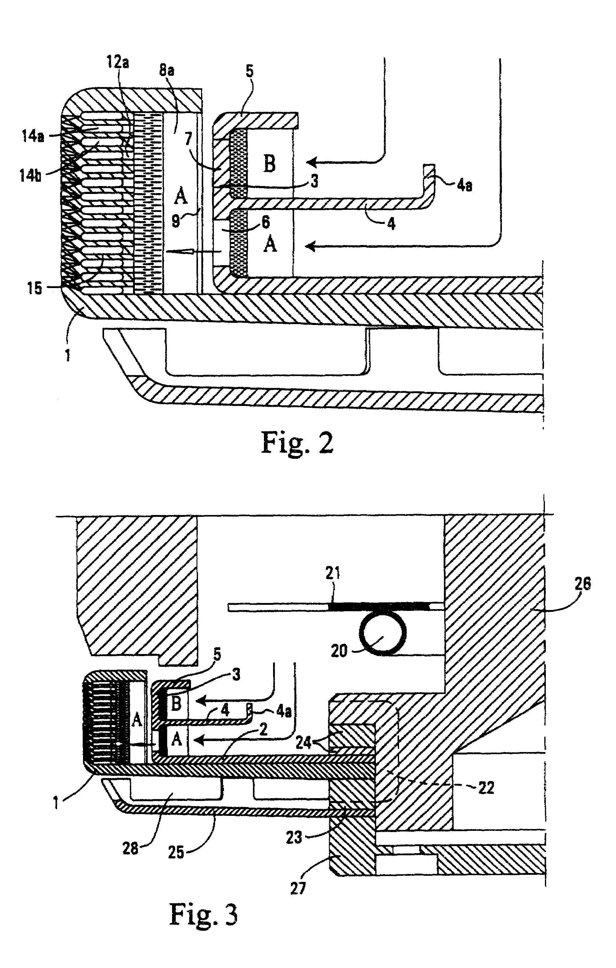
[0051]FIG. 1A is a transverse cross section of a spinner used to produce glass fibers through centrifugal force, heat, and aerodynamic pressure. The spinner 1 is basically a round dish having a peripheral circumference with holes drilled therein. The spinner has an upper top side flange but otherwise has an open top which permits molten glass to enter into the spinner and be forced to the circumference. In FIG. 1A there is mounted within the spinner a distributor spinner cup 2. The cup is fixedly mounted within the spinner. It has a peripheral wall or rim 3, a cup middle flange 4, and a middle flange upturned member 4A. The cup also has a top flange 5. The purpose of the cup is to separate two molten glasses A and B. Molten glass B is directed into the cup on top of the middle flange 4 whereas molten glass A falls inwardly of the cup middle flange upturned member 4A.

[0052]On examination of FIG. 2, one views that a molten stream of glass B descends upon the distributor spinner cup mi...


PUM

PropertyMeasurementUnit
temperaturesaaaaaaaaaa
coefficients of thermal expansionaaaaaaaaaa

Abstract

A spinner is adapted to produce a dual glass curly fiber component and a single straight glass fiber component insulation product. The spinner includes a plurality of horizontal channels within the spinner peripheral wall. The channels separate two molten glasses of differing coefficients of thermal expansion from one another which emerge outwardly together as a dual glass curly fiber. In other portions of the spinner peripheral wall a plurality of horizontal channels carry single molten glass which emerges as straight glass fibers. The spinner provides mechanical strength and resistance to reduce deformation of said spinner as well as creating a fiber glass product with stability, compressibility and expendability.

Description

BACKGROUND OF THE INVENTION[0001]The general field of this invention is a method and apparatus for a simultaneous, rotary process, high throughput capacity manufacturing of single-component and dual-component fibres from thermoplastic materials, and thermal and acoustical insulation products formed from a certain mixture of such fibres. More particularly, this invention relates to a method and apparatus for the combined centrifuging single-component, straight and dual-component, curly glass fibres, and products formed from these straight and curly glass wool type fibres.[0002]A typical glass fibre thermal or acoustical insulation product is made of rather short, single glass and basically straight glass fibres. A common method of manufacturing these glass wool type fibres is a rotary fiberizing process, where a single molten glass composition is forced by a high speed rotation through the orifices in the peripheral wall of a centrifuge, usually referred to as a spinner, and is furth...

Claims


Application Information

Patent Timeline
Patent Type & Authority Patents(United States)
IPC IPC(8): C03B37/04C03B37/075C03C25/34D01D5/18
CPCC03B37/044C03B37/0753C03C25/34D01D5/18Y10T428/2964Y10T428/2927C03C2213/04Y02P40/57
Inventor SKARZENSKI, JOSEPHCZASTKIEWICZ, WITOLD S.BANASZKIEWICZ, STAN
Owner OTTAWA FIBER
Learn More