
Cooling structure for high tension electrical equipment

a technology of electrical equipment and cooling structure, which is applied in the direction of heating types, electric apparatus casings/cabinets/drawers, heating types, etc., can solve the problems of excessive temperature increase of equipment, increase in the size and weight of the device, and high temperature inside the vehicle, so as to improve the degree of freedom with respect to form, the effect of improving the thermal insulation properties

Inactive Publication Date: 2006-02-28
HONDA MOTOR CO LTD
View PDF19 Cites 51 Cited by
  • Summary
  • Abstract
  • Description
  • Claims
  • Application Information

AI Technical Summary

Benefits of technology

[0007]The present invention was conceived in view of the above-described circumstances and has as its objective the provision of a cooling device for high tension electrical equipment which is compact, lightweight, and can efficiently cool the high tension electrical equipment.
[0010]Since the opening / closing action of the opening / closing valve is linked to the operation of the fan, the intake duct can be maintained in the closed state when the fan is not running. For example, even when the temperature of the air inside the vehicle has risen, the hot air inside the vehicle can be prevented from entering the equipment box.
[0011]As a result, by means of a simple and inexpensive structure in which an opening / closing valve consisting of an elastic material is provided inside the intake duct, it is possible to efficiently cool the high tension electrical equipment.
[0013]In this high tension electrical equipment cooling device, the thermoinsulating properties are improved by forming the intake duct from this foaming resin, and the device can be made lighter in weight as well. In addition, a greater degree of freedom with respect to form is conferred during production as compared to the case where the intake duct is formed by blow molding, etc.

Problems solved by technology

Namely, the temperature inside the vehicle can become very high when the vehicle has been stopped for a long period of time during the summer, for example.
Since the duct intake ports communicate with the interior of the vehicle, this high-temperature air inside the vehicle can enter into and flow through the ducts even when the cooling fan is off, potentially increasing the temperature of the equipment excessively.
However, this type of cooling device leads to an increase in the size and weight of the device, increasing costs required for forming its structure.

Method used


Image

  • Cooling structure for high tension electrical equipment
  • Cooling structure for high tension electrical equipment
  • Cooling structure for high tension electrical equipment

Examples


Embodiment Construction

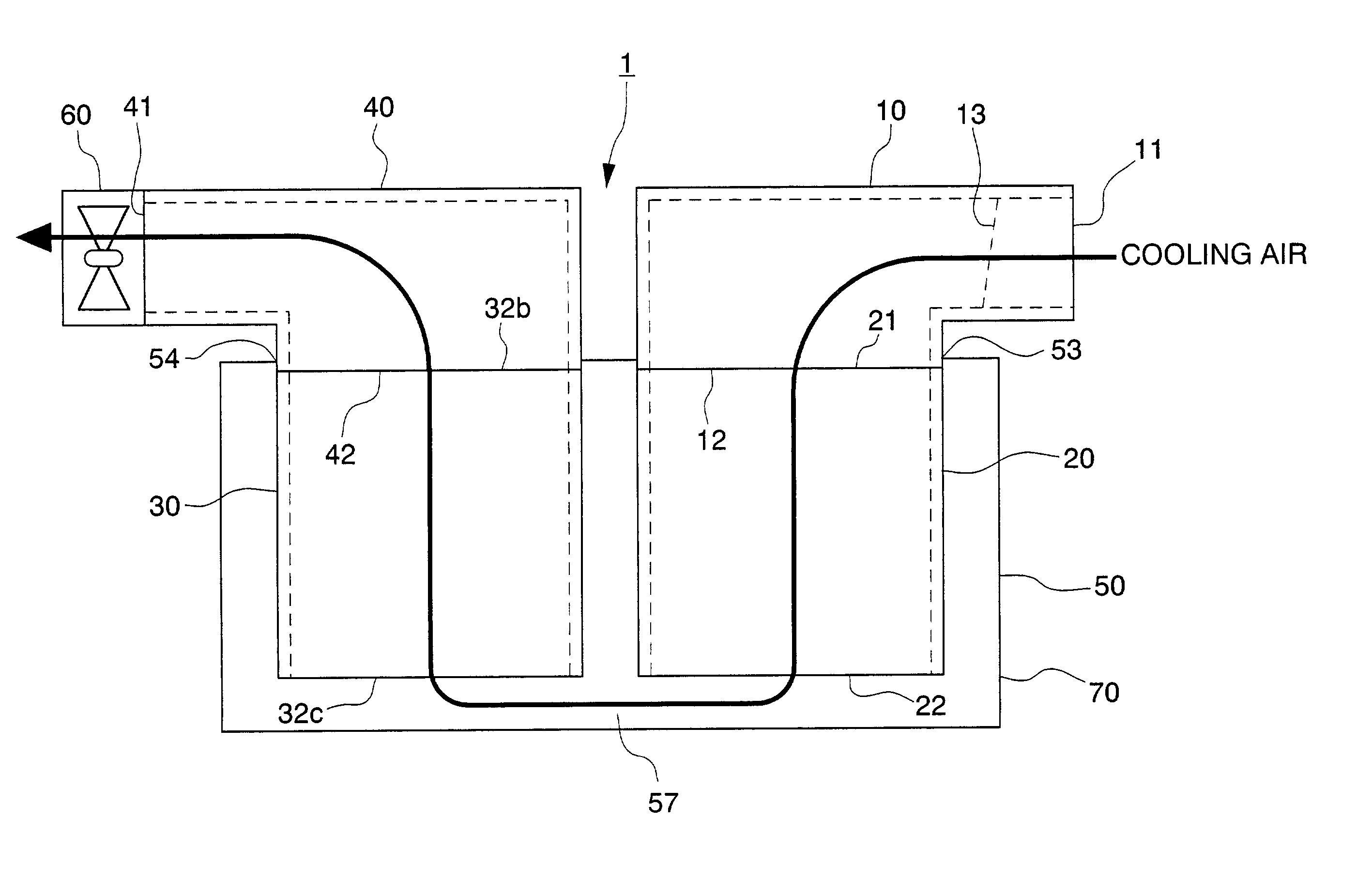
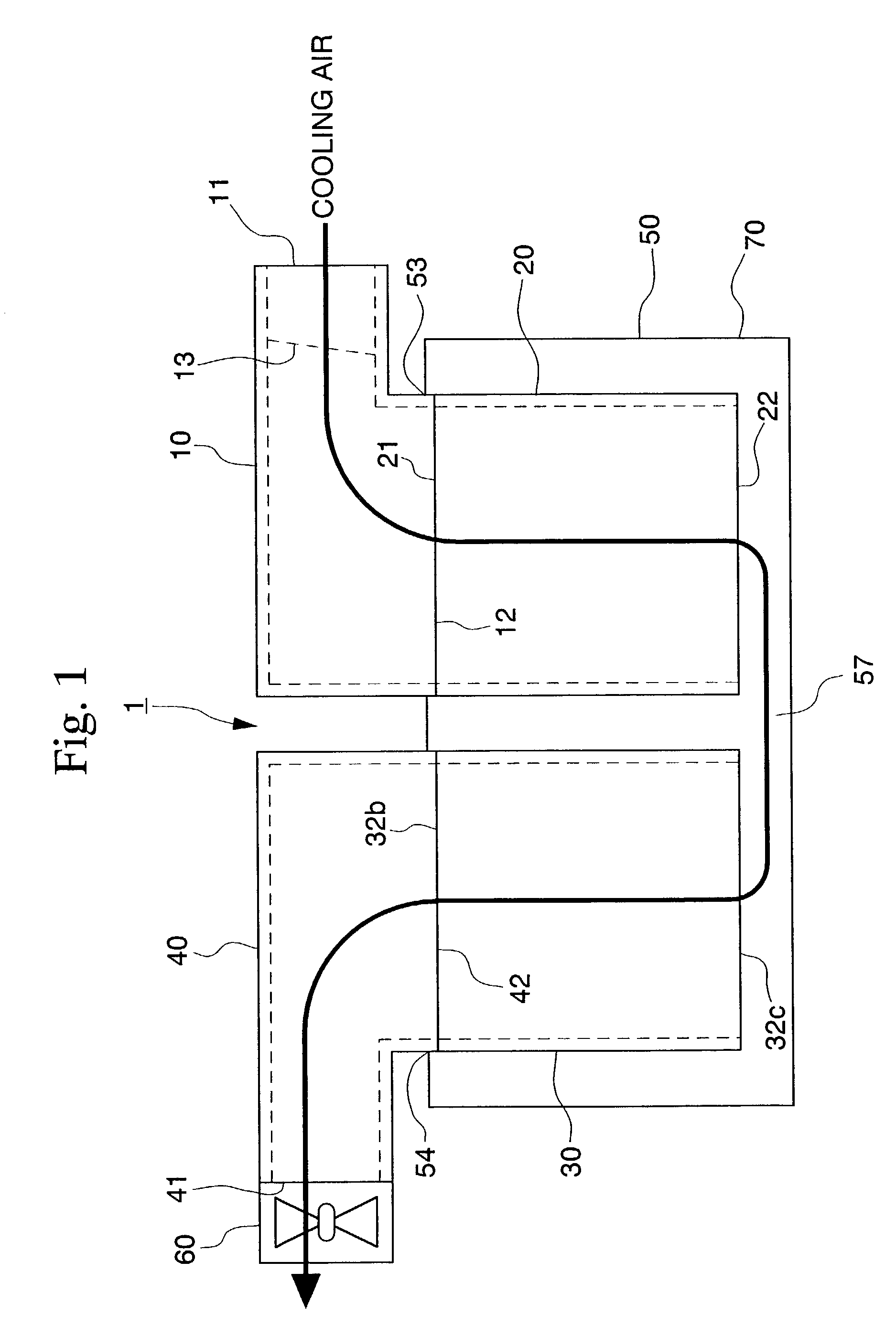
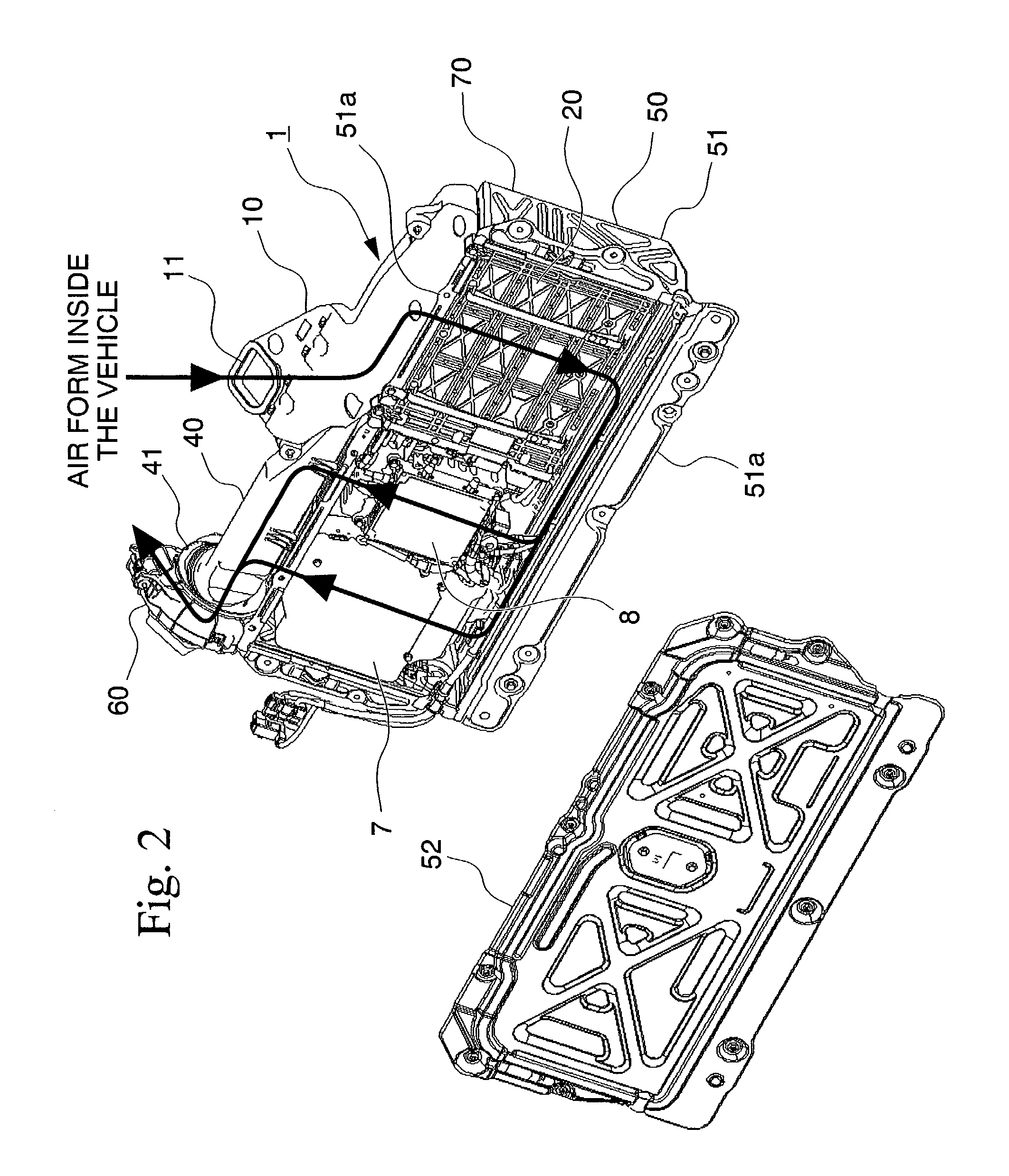
[0028]A first embodiment of a high tension electrical equipment cooling device of the present invention will now be explained with reference to FIGS. 1 through 10. Note that the vehicle in this embodiment is a hybrid vehicle in which, when power is supplied to the motor from the battery which is a direct current electric source, it is converted from direct current to alternating current by the inverter, and, when a portion of the engine output or the vehicle's kinetic energy is stored in the battery, the power is converted from an alternating current to a direct current by the inverter. Since the direct current voltage converted by the inverter is high voltage, a portion of it is reduced in voltage using a DC / DC converter. The high tension electrical equipment cooling device 1 according to this embodiment cools batteries, inverters and DC / DC converters.

[0029]An overview of the high tension electrical equipment cooling device 1 in this embodiment will now be explained with reference ...


PUM


Abstract

A high tension electrical equipment cooling structure for cooling batteries which supply electricity to the operating motor via an inverter, and the inverter using cooling air, and includes an equipment box for guiding cooling air introduced from a cooling air inlet port into a cooling air outlet port, and a fan for introducing cooling air from the cooling air inlet port. A shutter that includes an elastic material is disposed inside the intake duct. The shutter closes off the cooling air flow path, and when negative pressure is generated downstream of the shutter due to the operation of the fan, the shutter undergoes elastic deformation, and as a result, the cooling air flow path is opened.

Description

BACKGROUND OF THE INVENTION[0001]1. Field of the Invention[0002]The present invention relates to a cooling device for high tension electrical equipment, like condensers or inverters, that are installed in vehicles provided with a generator motor that rotates the vehicle's drive shaft, such as in hybrid and electric vehicles, for example.[0003]2. Description of the Related Art[0004]Cooling devices, such as the vehicular electrical equipment cooling device disclosed in Japanese Patent Application, First Publication No. Hei 11-195437 for example, are conventionally known that cool a battery or other such high tension electrical equipment by operating a cooling fan that takes in air from inside the vehicle via ducts that have intake ports communicating with the inside of the vehicle, and using this interior air from the vehicle to cool the high tension electrical equipment such as a battery.[0005]However, the temperature of the battery or other high tension electrical equipment can incr...

Claims


Application Information

Patent Timeline
IPC IPC(8): F28F27/00H05K5/00B60K1/04B60K6/20B60K6/22B60K6/28B60K6/40B60K11/06F01P1/06H01M10/60H01M10/613H01M10/625H01M10/643H01M10/6557H01M10/6563H01M10/6566H01M10/658H05K7/14H05K7/20
CPCH05K7/20909H05K7/20918
Inventor HASEGAWA, OSAMUAITAKA, KAZUHIKOTAKEDOMI, HARUMI
Owner HONDA MOTOR CO LTD
Learn More