Bus bar with L-shaped terminals

a technology of l-shaped terminals and bus bars, applied in the field of bus bars, can solve the problems of inpracticality and extensive manpower, and achieve the effects of enhancing work efficiency, reducing mixing, and enhancing recovery of iron

Inactive Publication Date: 2006-02-28
SUMITOMO WIRING SYST LTD
View PDF12 Cites 10 Cited by
  • Summary
  • Abstract
  • Description
  • Claims
  • Application Information

AI Technical Summary

Benefits of technology

[0022]In the case where the terminal piece is welded on the flat plate-like circuit body, it is preferable that an iron-based metal is interposed in the securing portion upon welding. Thus, if the welding material is made of the iron-based metal, it is possible to reduce mixing of a metal other than the iron-based metal in order to enhance recovery of iron.
[0023]The terminal piece may be secured to the flat plate-like circuit body through a conductive adhesive. Since a step of securi

Problems solved by technology

This work requires extensive manpower and is not practical.
Howev

Method used


Image

  • Bus bar with L-shaped terminals
  • Bus bar with L-shaped terminals
  • Bus bar with L-shaped terminals

Examples


first embodiment

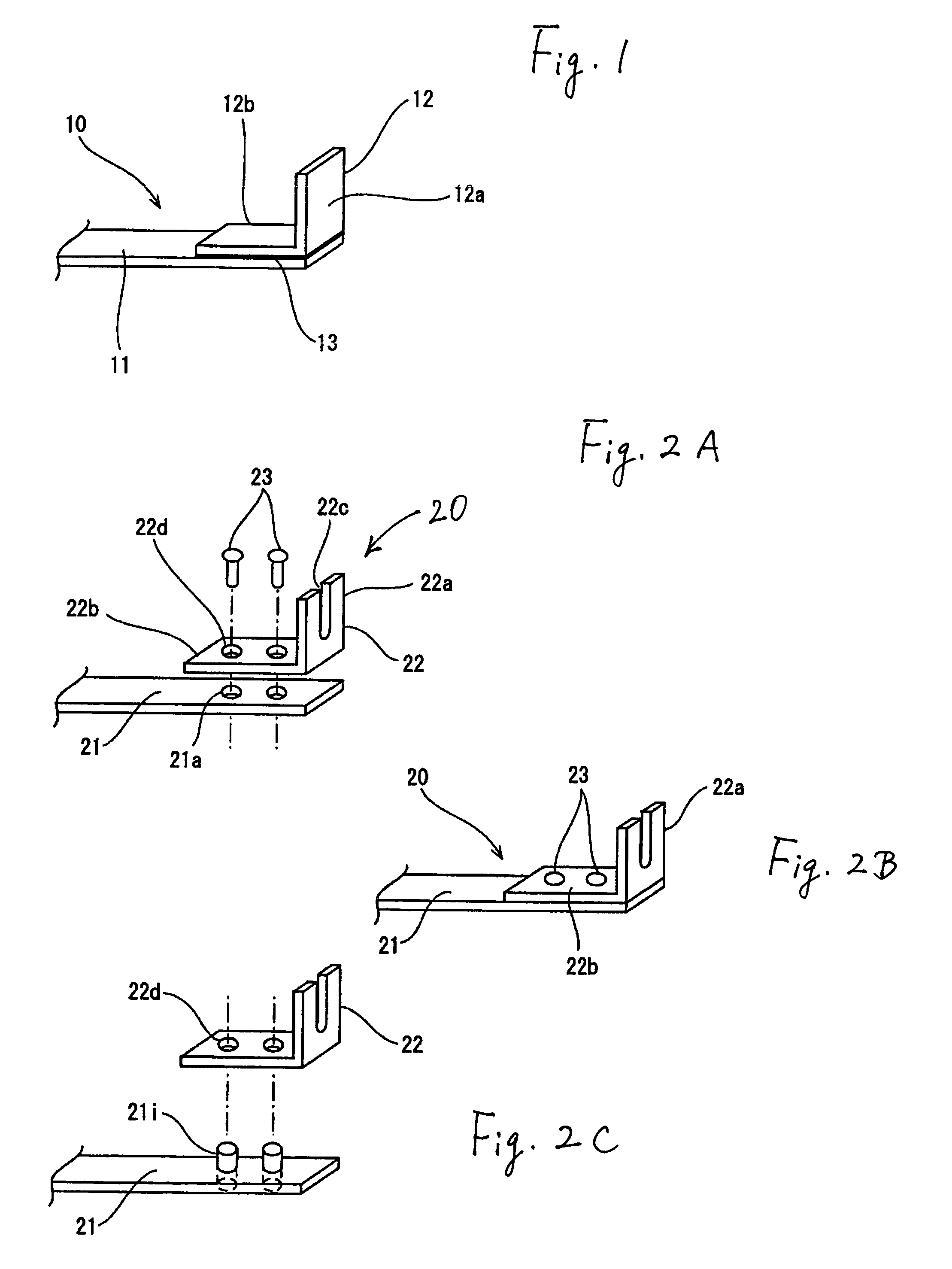
[0045]Embodiments of a bus bar in accordance with the present invention will be described below by referring to the drawings. FIG. 1 shows the bus bar in accordance with the present invention. A bus bar 10 shown in FIG. 1 is disposed on an insulation plate 3 to form an internal circuit in the electrical connection box 1 for an automobile shown in FIG. 7. The bus bar 10 is produced by punching an aluminum-based metal plate into a desired circuit configuration to form a flat plate-like circuit body 11. Another L-shaped terminal piece 12 is secured to an end of the flat plate-like circuit body 11.

[0046]The flat plate-like circuit body 11 may be made of pure aluminum or an aluminum alloy, such as Al—Mg, Al—Mn, Al—Mg—Si, Al—Zn—Mg, or Al—Si. Conductivity of pure aluminum is 60% of that of copper while conductivity of an aluminum alloy is 30% of copper. It will be preferable to use pure aluminum from a conductivity viewpoint.

[0047]The terminal piece 12 includes a tab 12a bent perpendicular...

second embodiment

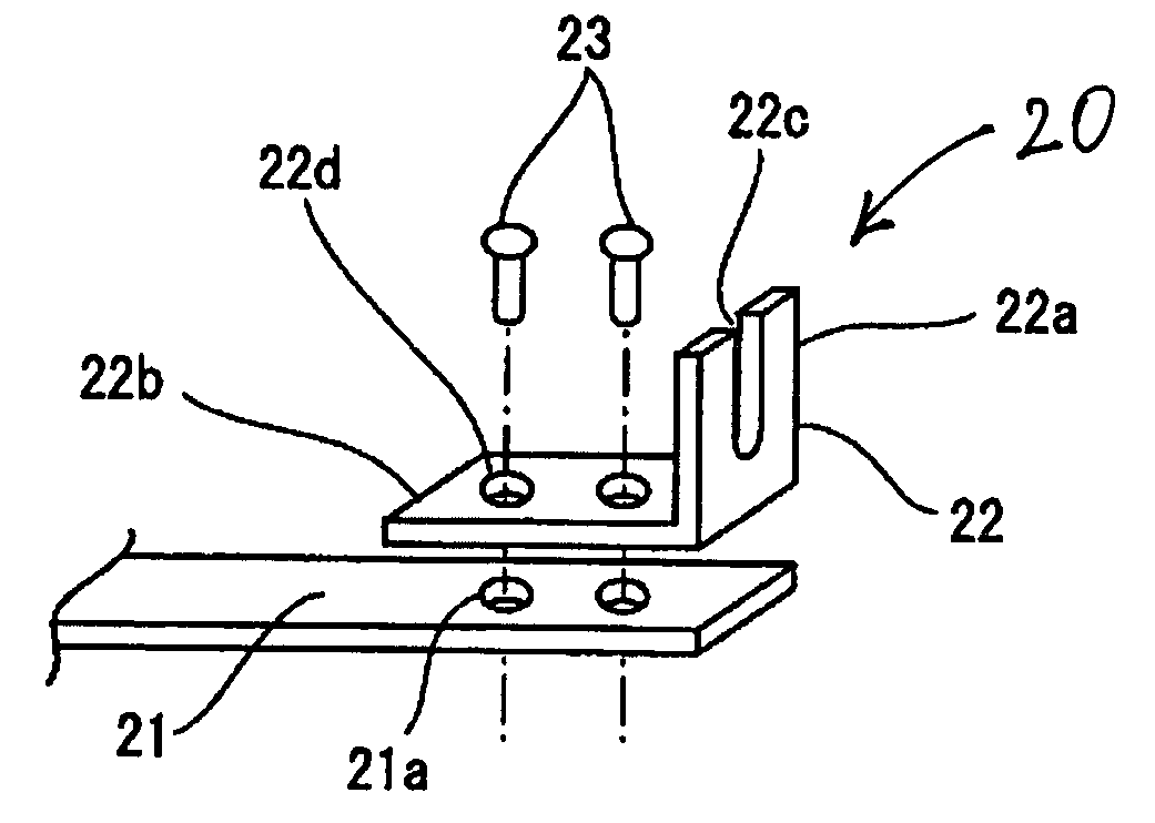
[0055]FIGS. 2A and 2B show the bus bar in accordance with the present invention.

[0056]In the second embodiment, a bus bar 20 includes a flat plate-like circuit body 21 and an L-shaped terminal piece 22. The circuit body is produced by punching an aluminum-base metal plate into a desired circuit configuration. The terminal piece 22 is made of a copper-based metal and secured on an end of the flat plate-like circuit body 21 by rivets 23. The rivets 23 are made of a metal other than a copper-based metal, preferably, an iron-based metal to suppress mixing of copper in iron.

[0057]Two through-holes 21a are formed in the flat plate-like circuit body 21 while two through-holes 22d are formed in a horizontal securing portion 22b of the terminal piece 22. The through-holes 22d have the same diameter and interval as those of through-hole 21a. In this embodiment, a press contact slot 22c is provided in a tab 22a of the terminal piece 22 to form a press contact tab.

[0058]As shown in FIG. 2C, pro...

third embodiment

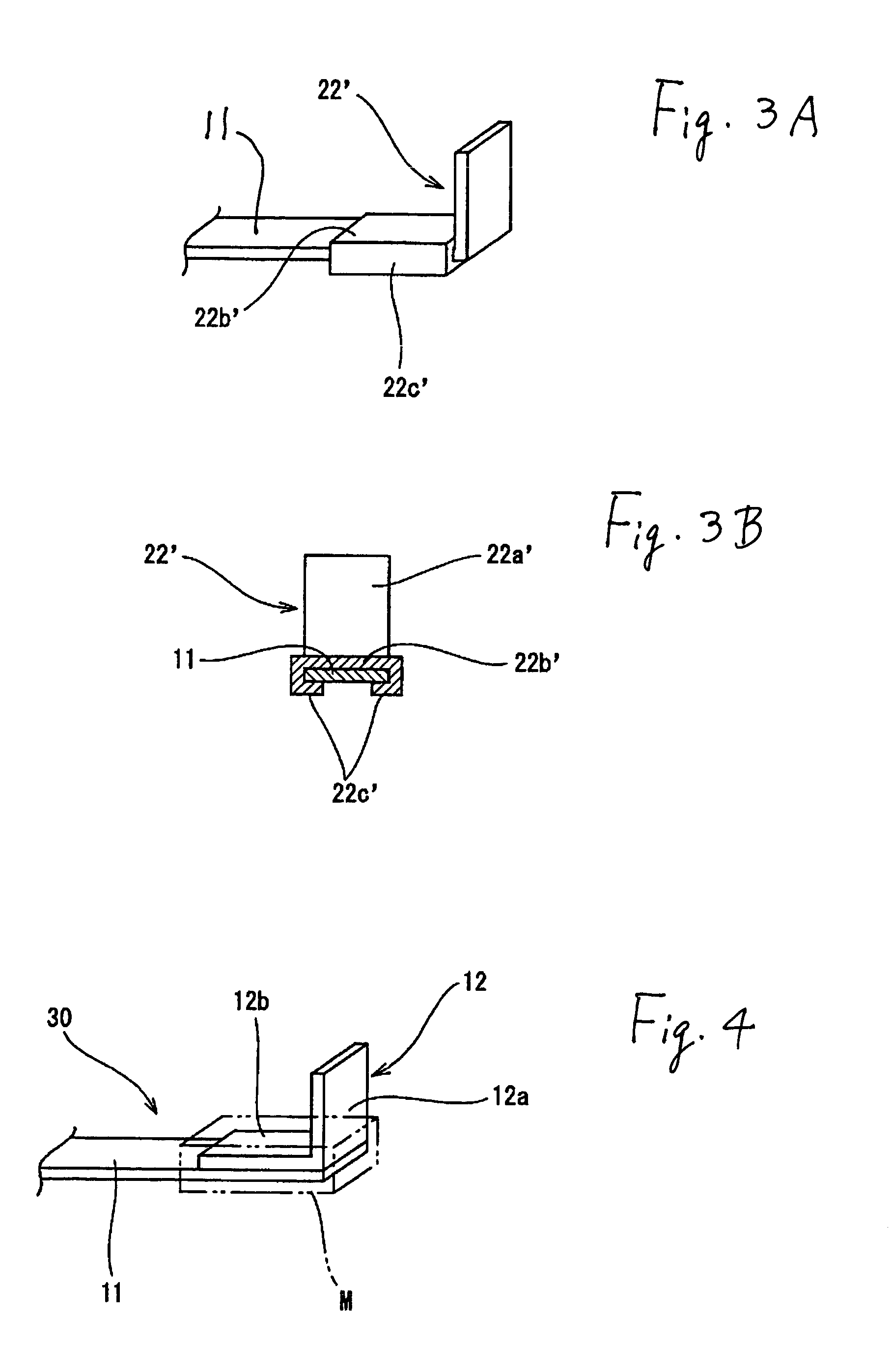
[0064]FIG. 4 shows the bus bar in accordance with the present invention.

[0065]In the third embodiment, a bus bar 30 includes a flat plate-like circuit body 11 made of the same aluminum-based metal as that in the first embodiment. A terminal piece 12 is made from copper-based metal. A securing portion 12b of the terminal piece 12 is placed directly on a surface of an end of the flat plate-like circuit body 11. An insulation resin is molded around the contact portions to form a molded portion M. A tab 12a of the terminal piece 12 projects outwardly from the molded portion M.

[0066]The terminal piece 12 and the flat plate-like circuit body 11 are made from different kinds of metals. Electric erosions will occur at the contact portions of the different kinds of metals, if water infiltrates the contact portions. However, the molded portion M prevents water from infiltrating the contact portions between the terminal pieces 12 and the flat plate-like circuit body 11. This protects the conta...


PUM


Abstract

A bus bar, with a desired circuit configuration contained in an electrical connection box to be mounted on an automobile, has an aluminum-based metal plate punched into a desired circuit configuration to form a flat plate-like circuit body. An L-shaped terminal piece is made from a copper-based metal plate. A horizontal portion of the L-shaped terminal piece is secured to the flat plate-like circuit body by welding a conductive adhesive, riveting, or caulking so that a vertical portion of the terminal piece projects from the circuit body to form a tab.

Description

CROSS-REFERENCE TO RELATED APPLICATIONS[0001]The entire disclosure of Japanese Patent Application No. 2002-265762 filed on Sep. 11, 2002 including the specification, claims, drawings and summary is incorporated herein by reference in its entirety.FIELD OF THE INVENTION[0002]The present invention relates to a bus bar and, more particularly, to a bus bar arranged to form an internal circuit in an electrical connection box, such as a junction box or the like, to be mounted on an automobile and made of a recyclable material.BACKGROUND OF THE INVENTION[0003]A bus bar, produced by punching an electrical conductive material, is contained in and forms an internal circuit in an electrical connection box, such as a junction box or the like.[0004]For convenience of explanation, a conventional bus bar will be described by referring to FIGS. 7 and 8. FIG. 7 is an exploded perspective view of a conventional electrical connection box for an automobile. FIG. 8 is an explanatory view that illustrate...

Claims


Application Information

Patent Timeline
IPC IPC(8): H01R4/02H01R13/02H02G3/16H01R4/04H01R4/62H05K3/20H05K3/40
CPCH01R4/62H05K3/4092H01R4/029H01R4/04H05K2201/0397H05K3/4015H05K3/202
Inventor YUASA, ERIKOYAMAKAWA, SHUJI
Owner SUMITOMO WIRING SYST LTD
Why Eureka
Try Eureka