Tissue aligning surgical stapler and method of use

a surgical stapler and tissue technology, applied in the field of surgical staplers, can solve the problems of enclosing too much tissue within the confines of closed staples, compromising both wound healing and resultant cosmetic appearance, and capturing too much tissue on closure, etc., to achieve rugged and reliable operation, simple construction, and low manufacturing cost

Inactive Publication Date: 2006-02-28
COLLINS JAMES R +2
View PDF9 Cites 24 Cited by
  • Summary
  • Abstract
  • Description
  • Claims
  • Application Information

AI Technical Summary

Benefits of technology

[0037]A still further object of this invention is to provide a surgical stapler that is simple in construction, inexpensive to manufacture, and rugged and reliable in operation.
[0038]These and other objects are accomplished by a surgical stapler having a tissue spacer at its forward end. The spacer is inserted between lateral sides of a wound to be closed and holds the tissue on lateral sides of the wound apart while the tines of a staple are driven into the tissue margins and bent around the staple bending surface of the staple anvil to draw the tissue captured between the tines toward each other. The tissue spacer has a width greater than the width of the staple bending surface of the anvil and less than the distance between the tines of the staple in an unbent condition such that when inserted between lateral sides of the wound it will space the facing tissue margins of the wound apart a distance sufficient to provide a metered amount of tissue lateral sides of the wound that will be captured between the tines and drawn together as the tines are bent toward each other to close the wound without crushing or overlapping of the captured tissue.

Problems solved by technology

The above-described patents are directed toward the closure of a wound with staplers and cumbersome combination approximation devices for the approximation of the wound edges prior to the placement of the surgical staples.
Currently, the conventional commercially available and most widely used staplers do not utilize cumbersome approximation devices but rather rely on the skill of the surgeon to approximate the margins of the wound.
If the tissue margins are closely approximated prior to the staples being placed, i.e. in common practice in contact with each other, there will be excessive tissue captured within the staple on closure.
When too little tissue is enclosed, gaps result.
Conversely, when too much tissue is enclosed initially, closure causes tissue compression so that both wound healing and resultant cosmetic appearance are compromised.
Several possible mechanical complications and consequences may result from enclosing too much tissue within the confines of the closed staples.
The crushing apposition of unlike tissues retards healing by requiring the deposition of vast quantities of fibrous connective tissue to bridge the faults thus resulting in significant scarring.
Additionally, crushing causes blood supply strangulation which compromises all healing.
Tensile strength of the tissues to be closed greatly affects healing time.
The high tissue strength of skin and fascia provide excellent staple holding characteristics but their relatively limited blood supply limits the healing process.
When tissue entrapment occurs within staples, blood supply can be severely compromised which additionally retards healing thus inviting tissue necrosis.
When too much tissue is enclosed within the confines of the staples so that tissue compression occurs, additional ischemia produced by the post surgical swelling compromises healing even further.

Method used


Image

  • Tissue aligning surgical stapler and method of use
  • Tissue aligning surgical stapler and method of use
  • Tissue aligning surgical stapler and method of use

Examples


second embodiment

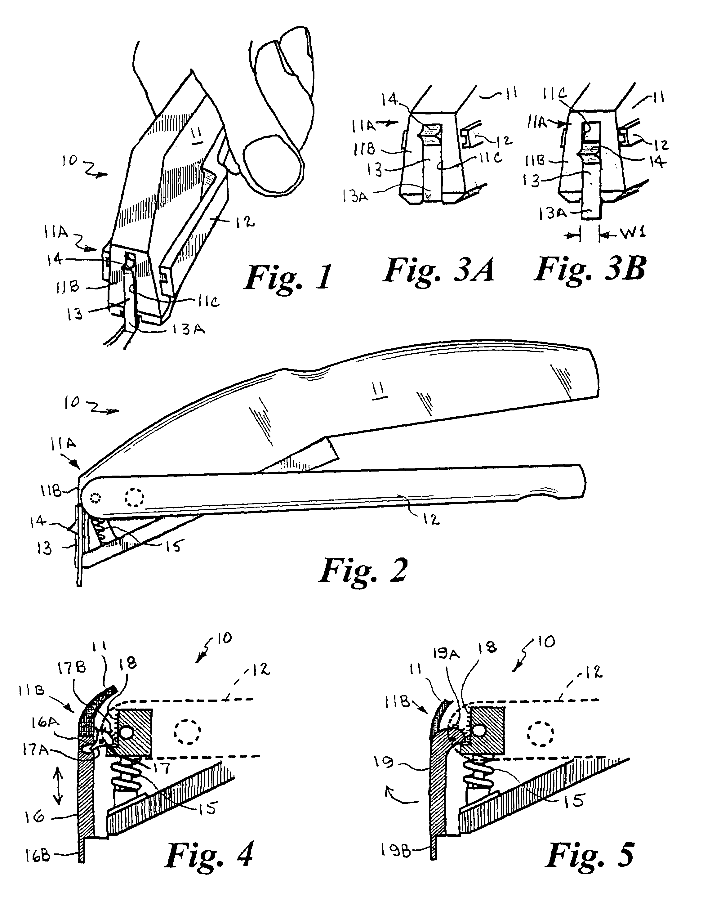
[0056]FIG. 4 shows a tissue spacer 16 which is raised and lowered vertically by the operation of the trigger 12 of the stapler. In this embodiment, the tissue spacer 16 is a generally rectangular member slidably mounted in a recess formed in the front end 11B of the body 11. The tissue spacer 16 has a recess 16A in its back side which receives a tongue 17A of a cam member 17 rotatably mounted in the body 11. The opposed end of the cam 17 has an arcuate toothed surface 17B similar to a pinion gear which is engaged with a mating toothed rack 18 connected with the forward end of the trigger 12. The forward end of the trigger 12 is spring biased to a raised position by the return spring 15. When the trigger 12 is squeezed, the tissue spacer 16 is moved vertically upward relative to the stapler body by the cam 17, and when the trigger is released, the spacer is returned to its lowered position. The release of the stapler trigger 12 also advances the next staple into position in a convent...

third embodiment

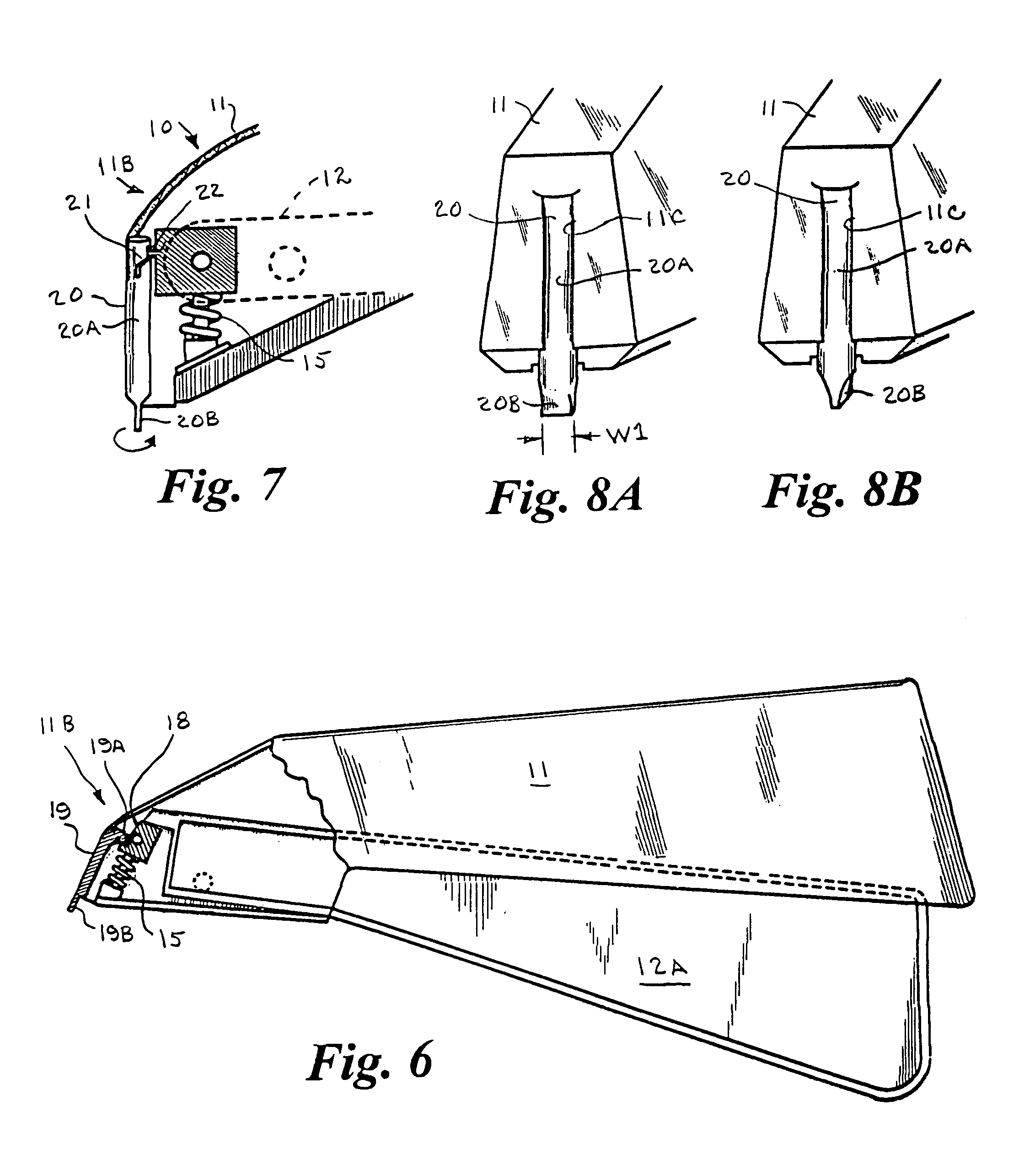
[0057]FIG. 5 shows the tissue spacer 19 which is pivoted between a raised and lowered position by the operation of the trigger 12 of the stapler. In this embodiment, the tissue spacer 19 is a generally rectangular member pivotally mounted in a recess formed in the front end 11B of the body 11. The upper end of the tissue spacer 19 has an arcuate toothed surface 19A similar to a pinion gear which is engaged with a mating toothed rack 18 connected with the forward end of the trigger 12. The forward end of the trigger 12 is spring biased to a raised position by the return spring 15. When the trigger 12 is squeezed, the lower end of the tissue spacer 19 is pivoted upwardly and outwardly relative to the stapler body 11 by the arcuate toothed surface 19A, and when the trigger is released, the spacer pivoted back to its lowered position. The release of the stapler trigger 12 also advances the next staple into position in a conventional manner. In its lower position, the lower end 19B of th...

fourth embodiment

[0059]FIGS. 7, 8A and 8B show a tissue spacer 20 that is rotatable relative to the stapler body 11. In this embodiment, the tissue spacer 20 has an elongate cylindrical shank portion 20A which is rotatably mounted in a recess 11C formed in the front end 11B of the body 11, and a flat generally rectangular lower end 20B which depends a short distance beyond the bottom of the front end of the stapler body. The lower end 20B of the tissue spacer 20 has a width W1. The upper end of the tissue spacer 20 has a spiral groove 21 which receives a pin 22 secured to the forward end of the trigger 12. The forward end of the trigger 12 is spring biased to a raised position by the return spring 15. As shown in FIG. 8A, when the trigger 12 is released or in the relaxed condition and its forward end is raised, the flat rectangular lower end 20B of the tissue spacer 20 is positioned transverse to the longitudinal axis of the stapler body. As shown in FIG. 8B, when the trigger 12 is squeezed, the pin...


PUM

PropertyMeasurementUnit
widthaaaaaaaaaa
distanceaaaaaaaaaa
mechanicalaaaaaaaaaa

Abstract

A surgical stapler having a tissue spacer at its forward end. The spacer is inserted between lateral sides of a wound to be closed and holds the tissue on lateral sides of the wound apart while the tines of a staple are driven into the tissue margins and bent around the staple bending surface of the staple anvil to draw the tissue captured between the tines toward each other. The tissue spacer has a width greater than the width of the staple bending surface of the anvil and less than the distance between the tines of the staple in an unbent condition such that when inserted between lateral sides of the wound it will space the facing tissue margins of the wound apart a distance sufficient to provide a metered amount of tissue lateral sides of the wound that will be captured between the tines and drawn together as the tines are bent toward each other to close the wound without crushing or overlapping of the captured tissue.

Description

BACKGROUND OF THE INVENTION[0001]1. Field of the Invention[0002]The present invention relates to surgical staplers. More particularly, it relates to a surgical stapler having a tissue spacer that aligns, spaces and supports the tissue margins of a wound during a stapling procedure to avoiding overriding or crushing of tissues by the surgical staple upon closure.[0003]2. Prior Art[0004]Surgical staplers, also known as skin staplers, are surgical stapling instruments for implanting and forming surgical staples in the skin or fascia of a patient to close a wound or incision. The typical surgical stapler comprises an elongated body having a forward portion and a rearward portion serving as a handle portion. The forward portion of the instrument body houses a staple pusher or driver attached to a staple driver actuator and a return spring for the staple driver actuator. A surgical staple magazine assembly is affixed to the lower edges of the instrument body forward portion. An anvil plat...

Claims


Application Information

Patent Timeline
Patent Type & Authority Patents(United States)
IPC IPC(8): A61B17/04
CPCA61B17/0684A61B2019/306A61B2017/081A61B2090/036
Inventor COLLINS, JAMES R.COLLINS, JOCK R.KAISER, CONARD E.
Owner COLLINS JAMES R
Why Eureka
Try Eureka