High-performance clock-powered logic

a clock-powered logic and clock-powered technology, applied in logic circuits, pulse techniques, reliability increasing modifications, etc., can solve the problems of reducing the speed at which logic circuitry can be clocked, imposing substantial capacitance, and corresponding substantial energy loss, so as to reduce the stress on digital circuitry components, reduce energy consumption in digital systems, and increase the speed at which digital systems can operate.

Inactive Publication Date: 2006-02-28
UNIV OF SOUTHERN CALIFORNIA
View PDF16 Cites 22 Cited by
  • Summary
  • Abstract
  • Description
  • Claims
  • Application Information

AI Technical Summary

Benefits of technology

[0017]Another object of the invention is to reduce energy consumption in digital systems.
[0018]A still further object of the invention is to increase the speed at which digital systems can operate.
[0019]A still further object of the invention is to reduce stress on digit

Problems solved by technology

One of the primary problems with long signal lines is the substantial capacitance which they impose.
As is well known, the presence of this substantial capacitance causes a corresponding substantial loss in energy while the signal lines are being driven between one logic state and another, such as commonly occurs during the serial delivery of digital data over the signal lines.
First, the circuitry usually requires the voltage of the clock signal to exceed the supply voltage, i.e., for the clock signal to run “hot.” This may stress certain digital devices by forcing them to run at voltage levels beyond the levels for which they were designed. The excess

Method used


Image

  • High-performance clock-powered logic
  • High-performance clock-powered logic
  • High-performance clock-powered logic

Examples


Embodiment Construction

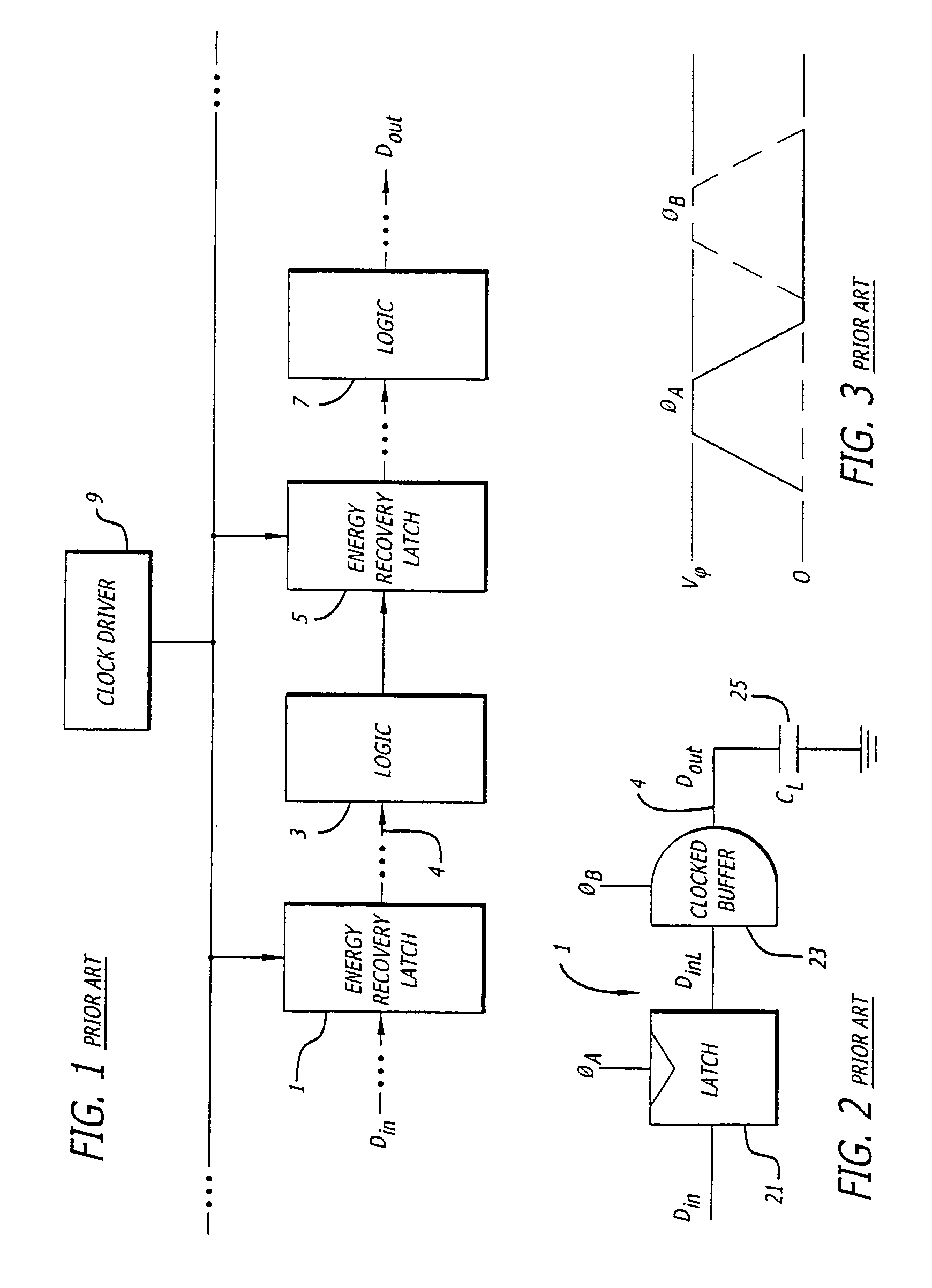
[0046]FIG. 1 is a block diagram of the architecture of a typical prior art clock-powered logic system.

[0047]As shown in FIG. 1, the digital signal to be processed, Din in this example, is delivered to an energy recovery latch 1. The output of the energy recovery latch 1 is delivered to digital logic 3.

[0048]Digital logic 3 represents the digital logic that processes the signal received from the energy recovery latch 1, typically over a long signal line, such as signal line 4.

[0049]The output of the digital logic 3 is delivered to a second energy recovery latch 5. The output of the second energy recovery latch 5 is delivered to a second set of digital logic 7. This architecture repeats until the digital signal, Din, is processed by all of the needed digital logic, leading to the generation of the output digital signal, Dout in this example. The energy recovery latches, including latches 1 and 5, operate under the control of a clock driver 9.

[0050]FIG. 2 is a block diagram of the prio...


PUM


Abstract

High performance clock-powered logic runs at below supply levels and reduces the need for faster digital logic circuitry. In a preferred embodiment, a clocked buffer (101) is used to drive the signal line. The receiving end of the line is connected to a jam latch (123), preferably followed by an n-latch (125), followed by the digital logic (109), and followed by a second n-latch (127). The first n-latch is eliminated in an alternative embodiment, preferably one that uses complementary data signals.

Description

CROSS-REFERENCE TO RELATED APPLICATIONS[0001]This application claims the benefit of the filing date of U.S. Provisional Application No. 60 / 144,520, entitled “High-Performance Clock-powered Logic,” filed Jul. 19, 1999, and U.S. Provisional Application No. 60 / 174,509 entitled “A Low-Power SRAM With Resonantly Powered Data, Address, Word and Bit Lines,” filed Jan. 5, 2000, the contents of both of which are incorporated herein by reference.GOVERNMENT LICENSE RIGHTS[0002]The invention was made with government support under DARPA Contract Nos. DAAL 01-95-K3528 and DABT63-96-C-0001. The government has certain rights in the invention.BACKGROUND OF INVENTION[0003]1. Field of the Invention[0004]This invention relates to digital systems and, more particularly, to digital systems that are driven by clock-powered logic, including adiabatic signals.[0005]2. Description of Related Art[0006]Digital systems include signal lines that carry digital signals, including data lines, address lines and cont...

Claims


Application Information

Patent Timeline
IPC IPC(8): H03K19/096
CPCH03K19/0019
Inventor ATHAS, WILLIAM C.TZARTZANIS, NESTORMAO, WEIHUAPETERSON, LENA
Owner UNIV OF SOUTHERN CALIFORNIA
Why Eureka
Try Eureka