High-speed low-noise charge pump

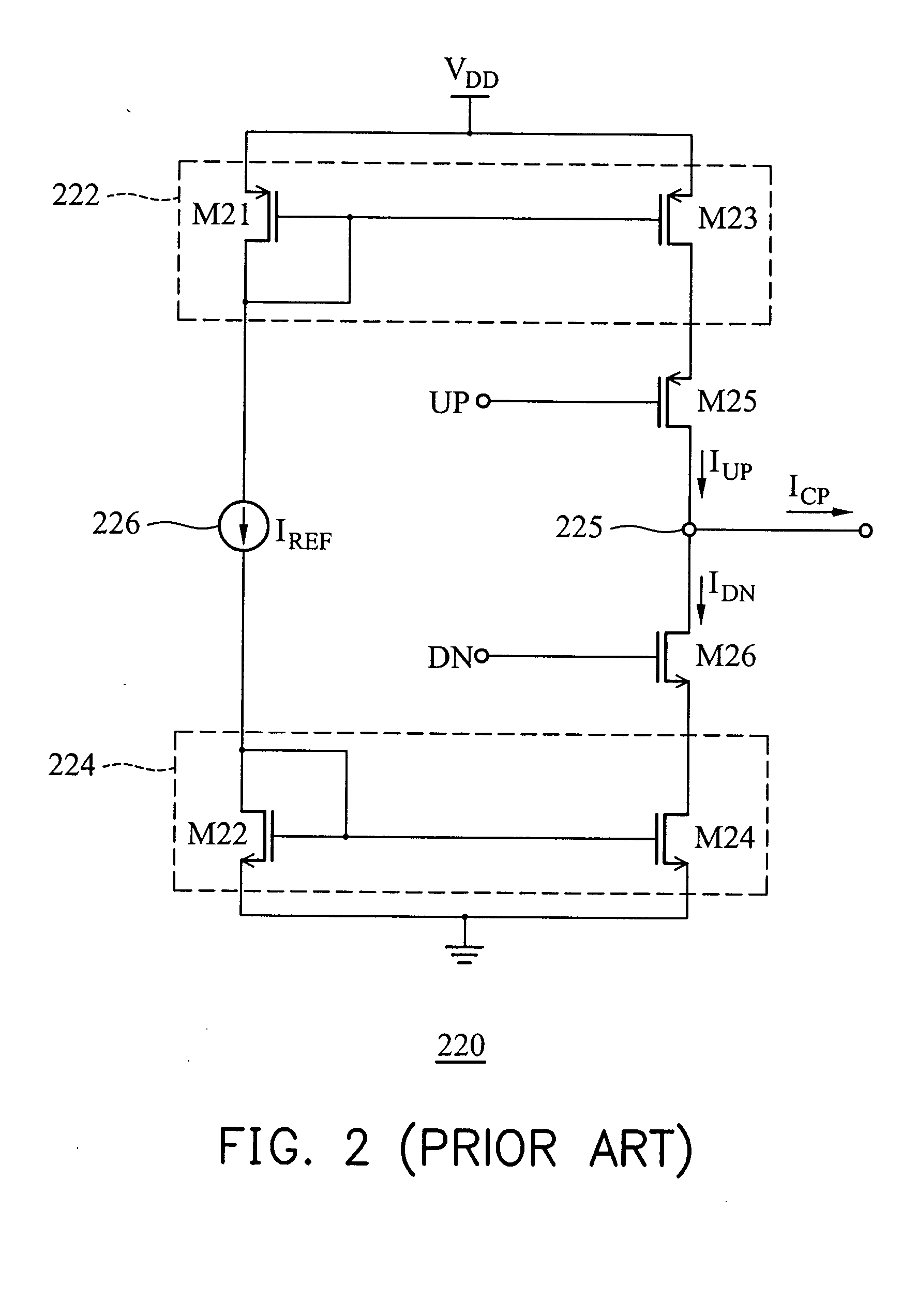
a charge pump, low-noise technology, applied in the direction of oscillator generator, pulse automatic control, pulse technique, etc., can solve the problems of limiting the range of voltages over which the output current may be generated, high switching noise of the conventional charge pump b>220/b>, and high switching noise while operating at higher speed, so as to achieve low switching noise, improve current matching, and high switching speed

Inactive Publication Date: 2006-02-28
VIA TECH INC
View PDF8 Cites 23 Cited by
  • Summary
  • Abstract
  • Description
  • Claims
  • Application Information

AI Technical Summary

Benefits of technology

[0011]It is an object of the present invention to provide a charge pump suitable for wireless communications, which features high switching speed, low switching noise and better current matching.

Problems solved by technology

Nevertheless, the conventional charge pump 220 suffers from high switching noise while operating at higher speed.
In addition to high switching noise, the use of the conventional charge pump 220 limits the range of voltages over which the output current may be generated.
Therefore, the conventional charge pump 220 is not applicable to high-speed applications.
However, the switching speed is still not high enough because Rhee's charge pump requires a considerable turn-on time to deal with a large amount of charge accumulation on the parasitic capacitance of MOS transistors.
Furthermore, Rhee's charge pump may have a current matching problem caused by variations of manufacturing process.

Method used


Image

  • High-speed low-noise charge pump
  • High-speed low-noise charge pump
  • High-speed low-noise charge pump

Examples


Embodiment Construction

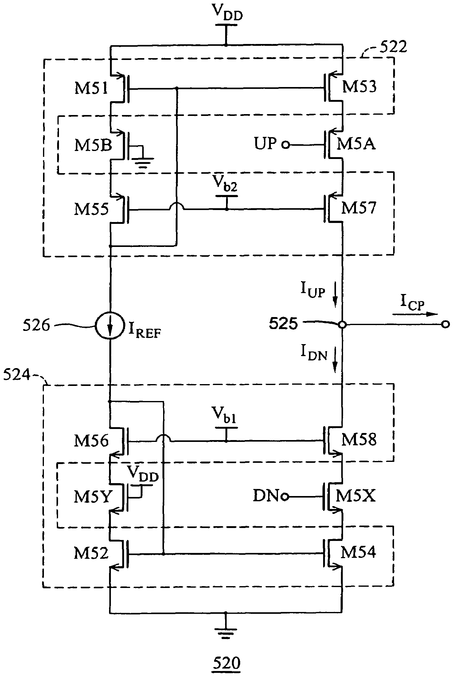
[0021]With reference to FIG. 3, a first embodiment of a charge pump 320 in accordance with the invention is illustrated. Each transistor described herein is either a p-channel or n-channel MOS transistor having a gate, a drain and a source. Since a MOS transistor is typically a symmetrical device, the true designation of “source” and “drain” is only possible once a voltage is impressed on the terminals. The designations of source and drain herein should be interpreted, therefore, in the broadest sense. The charge pump 320 includes a “pump-up” current mirror 322 and an associated switching transistor M3A. A transistor M3B in the branch M31–M35 is the counterpart of the switching transistor M3A. The charge pump 320 also includes a “pump-down” current mirror 324 and an associated switching transistor M3X. Similarly, a transistor M3Y in the branch M32–M36 is the counterpart of the switching transistor M3X. The “pump-down” current mirror 324 is coupled to a reference current source 326 p...


PUM


Abstract

A high-speed, low-noise charge pump for use in a phase-locked loop. The charge pump is constituted by first and second cascode current mirrors, as well as first and second switching transistors. The first cascode current mirror includes a first output mirror transistor and a first output cascode transistor. The first switching transistor is interposed between the first output mirror and the first output cascode transistors. During assertion of a first control signal, the first switching transistor is turned on so a first mirror current can flow through an output node. Likewise, the second cascode current mirror includes a second output mirror transistor and a second output cascode transistor. The second switching transistor is interposed between the second output mirror and the second output cascode transistors. During assertion of a second control signal, the second switching transistor is turned on so the second mirror current can flow through the output node.

Description

BACKGROUND OF THE INVENTION[0001]1. Field of the Invention[0002]The invention relates to a charge-pump circuit, and more particularly to a high-speed, low-noise charge pump for use in a phase-locked loop (PLL).[0003]2. Description of the Related Art[0004]In recent years, the rapid growth of cellular communications systems has motivated an increasing demand for high performance integrated radio frequency (RF) components. One of the most important building blocks of these systems is the local oscillator (LO). The need for a well defined and highly stable signal for the local oscillator makes necessary the use of phase-locked loop (PLL) techniques to satisfy the stringent requirements of wireless standards. With reference to FIG. 1, a block diagram of a typical PLL 100 is illustrated. Briefly, the PLL 100 includes a phase detector 110, a charge pump 120, a loop filter 130, a voltage-controlled oscillator (VCO) 140 and a frequency divider 150. The PLL 100 receives a reference clock sign...

Claims


Application Information

Patent Timeline
Patent Type & Authority Patents(United States)
IPC IPC(8): H03L7/093H03L7/089
CPCH03L7/0895
Inventor CHEN, CHUN-CHIEHLIN, JYH-FONG
Owner VIA TECH INC
Why Eureka
Try Eureka