Replacement heart valve sizing device

a heart valve and replacement technology, applied in the field of aortic valve replacement, can solve the problems of time-consuming and somewhat inexact procedure, conventional plugs cannot be used to correctly size the replacement valve, and fails to teach or suggest any alternative sizing mechanism, etc., to facilitate the choice of a replacement valve

Inactive Publication Date: 2006-03-07
MEDICAL SYST
View PDF49 Cites 118 Cited by
  • Summary
  • Abstract
  • Description
  • Claims
  • Application Information

AI Technical Summary

Benefits of technology

[0008]It is therefore an object of this invention to provide a percutaneous heart valve sizing mechanism which is advanceable with the v

Problems solved by technology

As can probably be ascertained, the use of plugs to correctly size the replacement valve results in a time consuming and somewhat inexact procedure.
One problem with the percutaneous approac

Method used


Image

  • Replacement heart valve sizing device
  • Replacement heart valve sizing device
  • Replacement heart valve sizing device

Examples


Embodiment Construction

[0028]Aside from the preferred embodiment or embodiments disclosed below, this invention is capable of other embodiments and of being practiced or being carried out in various ways. Thus, it is to be understood that the invention is not limited in its application to the details of construction and the arrangements of components set forth in the following description or illustrated in the drawings.

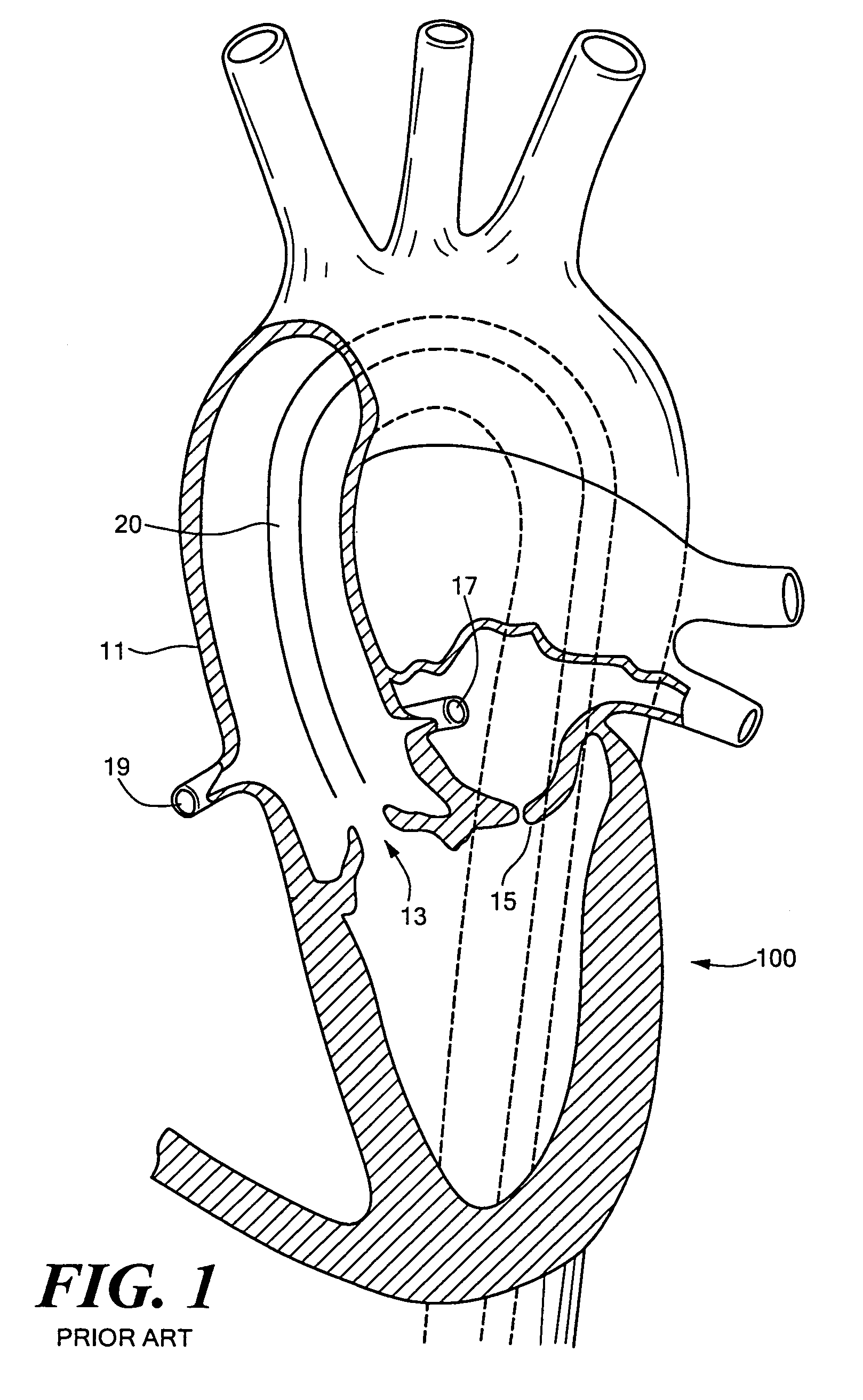
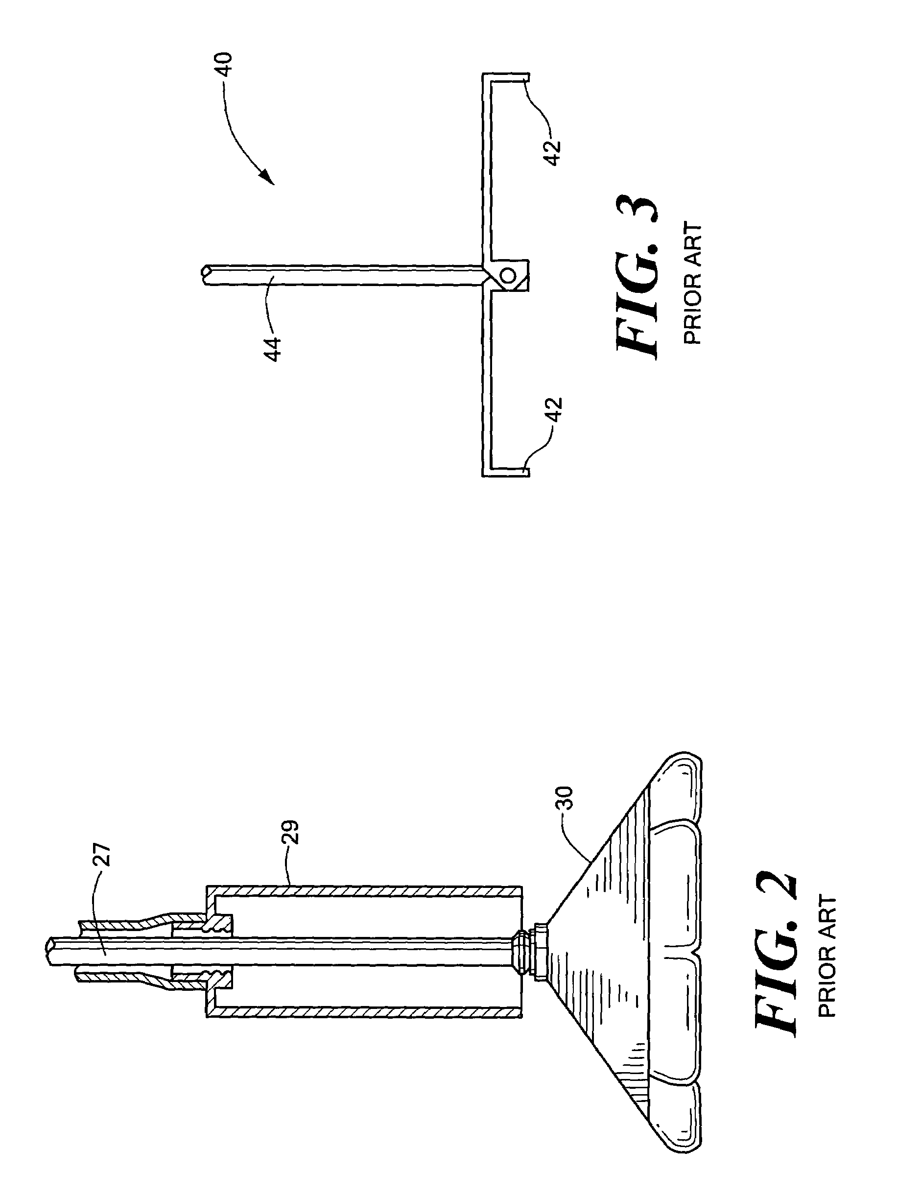
[0029]FIG. 1 schematically shows heart 100 with aorta 11, aortic valve 13, mitral valve 15, and coronary arteries 17 and 19. The idea behind percutaneous valve replacement surgery is to deliver a catheter 20 proximate valve 13 to resect it and to secure a replacement prosthetic valve in place. Resecting the native valve, however, is problematic. Those skilled in the art have devised inflatable barriers such as barrier 30, FIG. 2 used to trap tissue during resection. See also U.S. Pat. No. 6,287,321 and Published U.S. Patent Application No U.S. 2002 / 0095116 A1. Barrier 30 traps any tissue cu...


PUM


Abstract

A heart valve sizing system featuring a lumen advanceable in vasculature, an inside caliper device at the distal end of the lumen, and a readout for reading the dimension gauged by the inside caliper device. In the preferred embodiment, the inside caliper device includes a four bar linkage with first and second opposing pivot points and third and fourth opposing pivot points and a push rod connected to the second pivot point for alternatively urging the third and fourth pivot points together when extended and urging the third and fourth pivot points apart when retracted to gauge the inside dimension of the vasculature.

Description

FIELD OF THE INVENTION[0001]This invention relates to aortic valve replacement.BACKGROUND OF THE INVENTION[0002]Currently, replacement of a malfunctioning heart valve is accomplished by a major open-heart surgical procedure requiring general anesthesia, full cardio-pulmonary bypass with complete cessation of cardio-pulmonary activity, and a long period of hospitalization and recuperation. In most cases, the native valve is resected (cut-out) and the replacement valve then installed.[0003]The appropriate size replacement valve is determined using plugs. The surgeon chooses a plug from a tray of plugs increasing in size by 1 mm increments or so. If the chosen plug is too loose in the patient's aorta, a larger plug is chosen; if the plug chosen is to large to fit in the patient's aorta, a smaller plug is chosen, and so on until the chosen plug fits just right. Then, a replacement valve of a size corresponding to the size of the correct plug is installed and stitched in place. As can pr...

Claims


Application Information

Patent Timeline
IPC IPC(8): A61B1/005A61B5/107A61F2/24
CPCA61F2/2496A61B5/1076
Inventor RUDKO, ROBERT I.YEOMANS, JR., RICHARD P.
Owner MEDICAL SYST
Why Eureka
Try Eureka