Building structure element and stiffening plate elements for such an element

Inactive Publication Date: 2006-03-07
DANIELSSON ERIK
View PDF39 Cites 8 Cited by
  • Summary
  • Abstract
  • Description
  • Claims
  • Application Information

AI Technical Summary

Benefits of technology

[0006]One object of the present invention is to provide a joint acting structure, including a plurality of stiffening plate elements and a thin concrete slab, employed in various building structure elements, such as walls and floor structures. Since a thin concrete slab is used, the stiffening elements need to be anchored shallowly, putting great demands on the adherence between the embedded portion of the stiffening plate elements and the concrete. Furthermore, it is of great importance that this adherence may be obtained in a simple and inexpensive way.

Problems solved by technology

Since a thin concrete slab is used, the stiffening elements need to be anchored shallowly, putting great demands on the adherence between the embedded portion of the stiffening plate elements and the concrete.

Method used


Image

  • Building structure element and stiffening plate elements for such an element
  • Building structure element and stiffening plate elements for such an element
  • Building structure element and stiffening plate elements for such an element

Examples


first embodiment

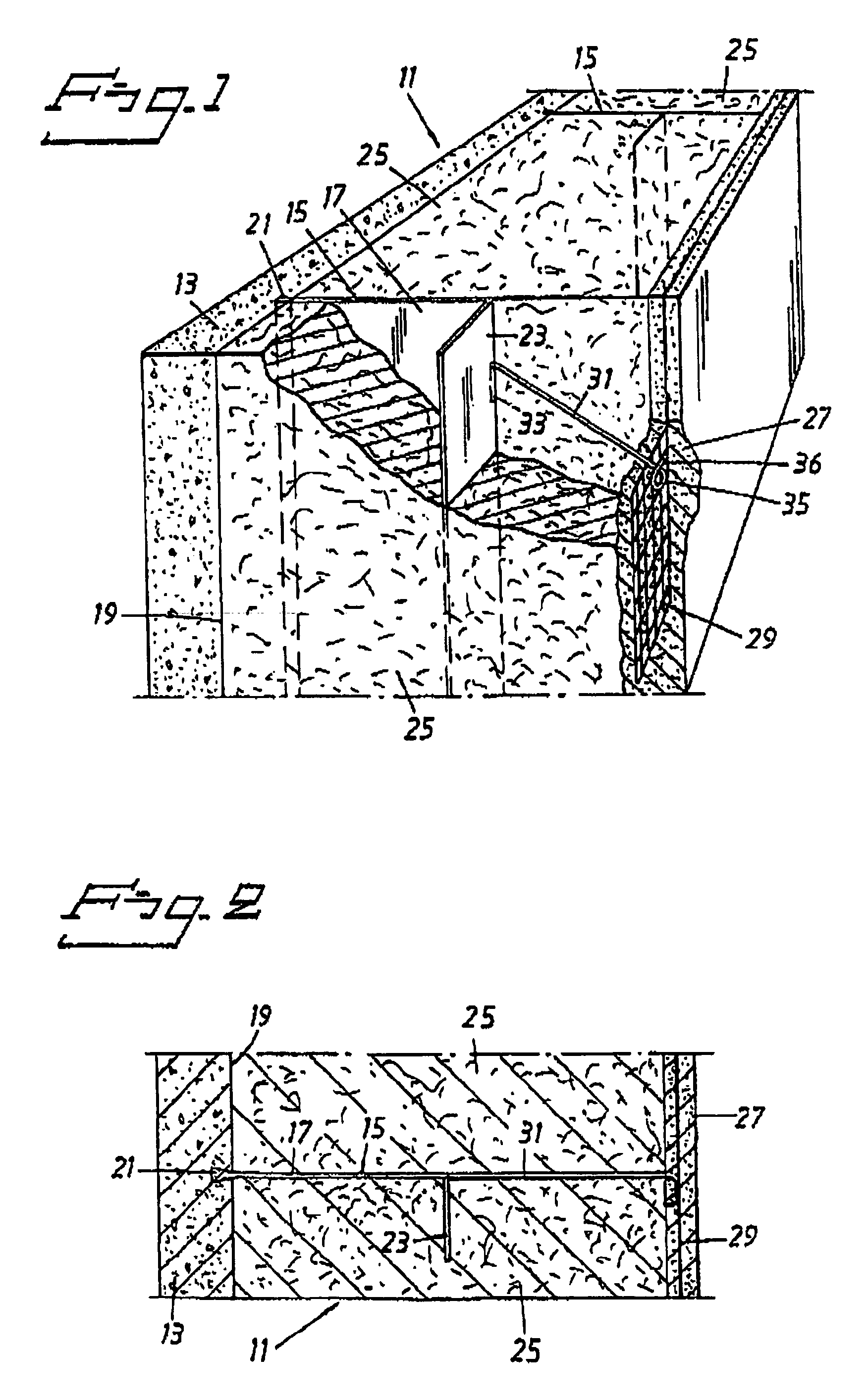
[0019]FIGS. 1 and 2 show a supporting wall structure element 11 according to the invention, where the wall structure element 11 comprises a vertical, reinforced, preferably steel fibre reinforced, concrete slab 13 with a plurality of embedded stiffening plate elements 15, and intended to form a supporting external- or intermediate wall, where the stiffening plate element 15 aiming to stiffen the wall structure element 11 so it more easily can absorb stresses due to compression or bending moments.

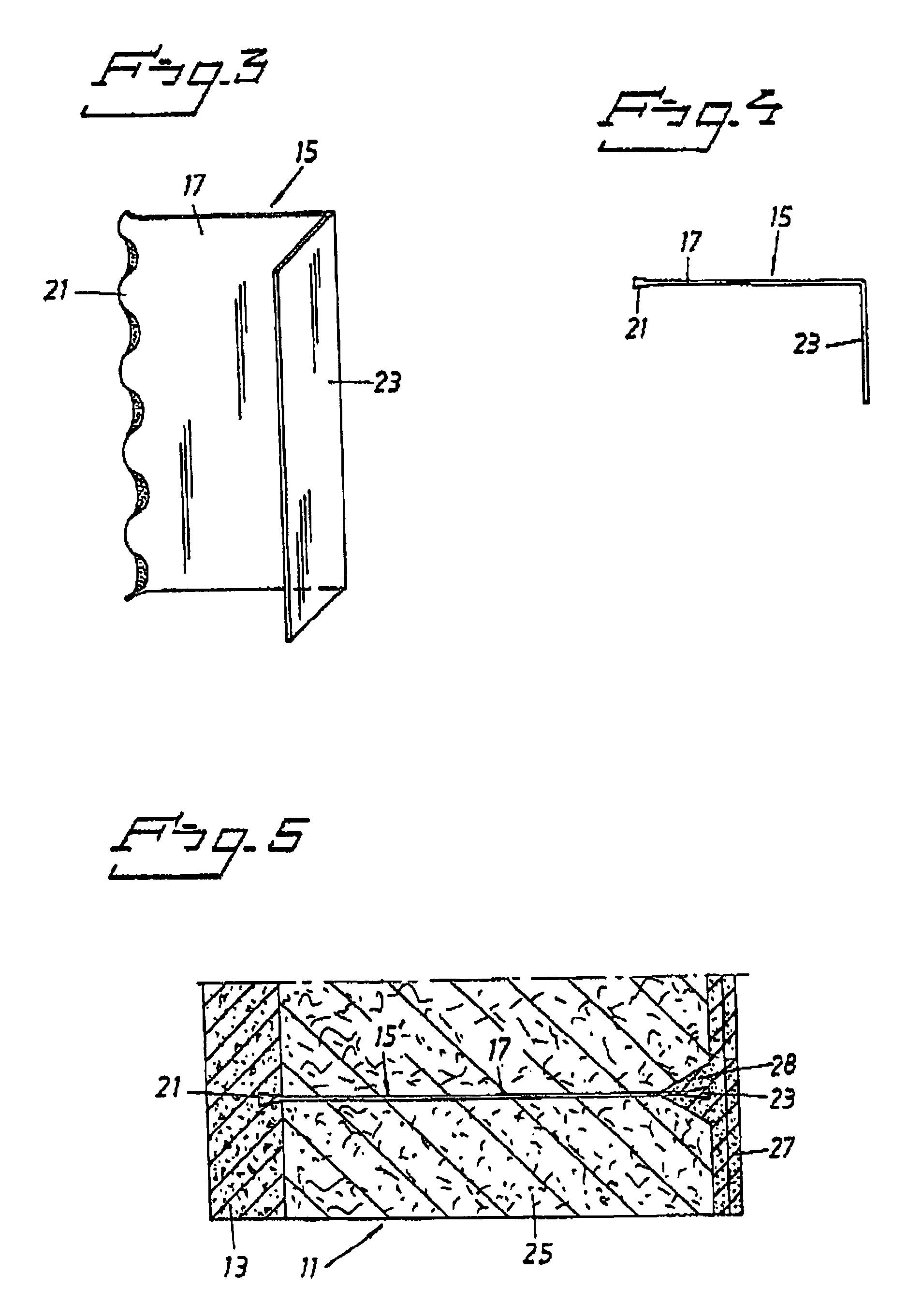
[0020]The stiffening plate elements 15 are substantially vertically orientated, horizontally separated, as well as discrete and parallel in relation to each other, each having a web 17, where a considerable portion of the web protrudes freely and substantially perpendicularly from a first side defining surface 19 of the concrete slab 13. The stiffening plate elements 15, which are not mutually joined, are anchored in the concrete slab 13 by means of a first longitudinal edge portion 21 of th...

second embodiment

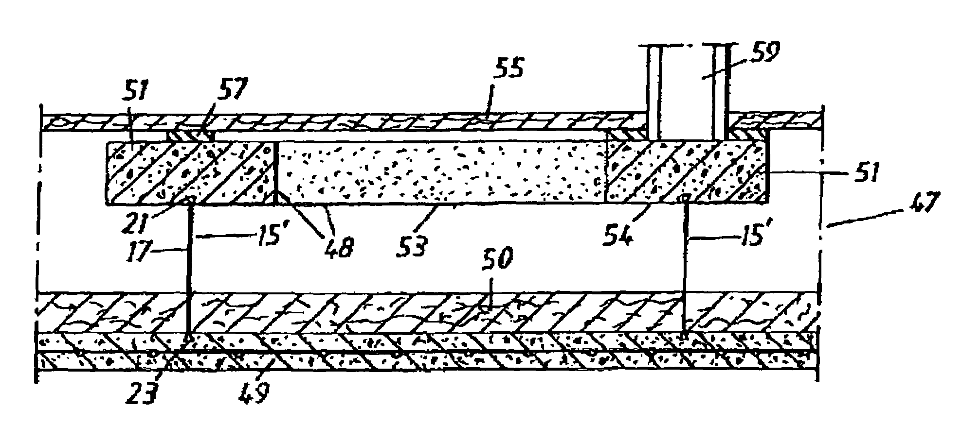
[0034]At a lower edge of each batten element 51 stiffening plate elements 15′ in FIG. 5 is embedded by means of a first, corrugated longitudinal edge portion 21 of the web 17, as earlier described in connection with the wall structure element. Accordingly, the stiffening plate elements are horizontally separated, discrete and parallel in relation to each other. A considerable portion of the web 17 protrudes freely and extends substantially perpendicularly, vertically out from the lower surface 54 of the batten elements 51, and the stiffening plate elements 15′ extend along the batten elements 51. The second longitudinal edge portion 23 of the web is anchored in the concrete slab 49 in an analogous manner. Consequently, the frame work 48 will rest on the lower concrete slab 49 by means of the stiffening plate elements 15′, and the corrugation will provide an efficient adherence in the concrete that will absorb the shear stresses acting on the stiffening plate elements parallelly wit...


PUM


Abstract

A prefabricated, supporting building structure element, such as wall elements (11), floor structures (47) or the like includes a reinforced concrete slab (13) having a plurality of discrete, parallel, horizontally separated, not mutually joined, longitudinally extended stiffening plate elements (15), each having a web (17) with a first longitudinal edge portion (21) embedded in the concrete, such that a considerable portion of the web (17) protrudes freely, substantially perpendicularly from a first side defining surface of the concrete slab (13). The longitudinal edge portion (21) exhibits a substantially wave shaped corbelling from the plane of the web (17).

Description

FIELD OF THE INVENTION[0001]The present invention relates to a prefabricated, supporting building structure element, such as wall elements, floor structures or the like comprising a reinforced concrete slab having a plurality of discrete, parallel, horizontally separated, not mutually joined, longitudinally extended stiffening plate elements, each having a web with a first longitudinal edge portion embedded in the concrete, such that a considerable portion of the web protrudes freely, substantially perpendicularly from a first side defining surface of the concrete slab.[0002]The invention also relates to a plate element for stiffening a building structure element of reinforced concrete, such as wall elements, floor structures or the like, where the plate element consists of a longitudinally extended web with a first longitudinal edge portion to be anchored in the concrete with a considerable portion of the web freely protruding from the concrete.BACKGROUND OF THE INVENTION[0003]With...

Claims


Application Information

Patent Timeline
Patent Type & Authority Patents(United States)
IPC IPC(8): E04B2/46E04C1/40E04B2/58E04B2/86E04B5/38E04B5/02E04C2/04E04C2/16E04C2/28E04C2/38
CPCE04C2/04E04B5/04
Inventor DANIELSSON, ERIK
Owner DANIELSSON ERIK
Why Eureka
Try Eureka