


Quick Research
Generate reliable direction feasibility study reports for your R&D in just a few steps.

Technical Q&A
Discover and master advanced knowledge NOW. Basics, ideas, possibilities, all at once.

Find Solutions
As an expert in R&D theories, this can generate solutions to your technical problems instantly.

Evaluate Feasibility
Analyze your overall solution with one click, know your potential R&D risks in advance.

Monitor Landscape
Get weekly tech updates, stay abreast of the latest tech innovations and key insights.
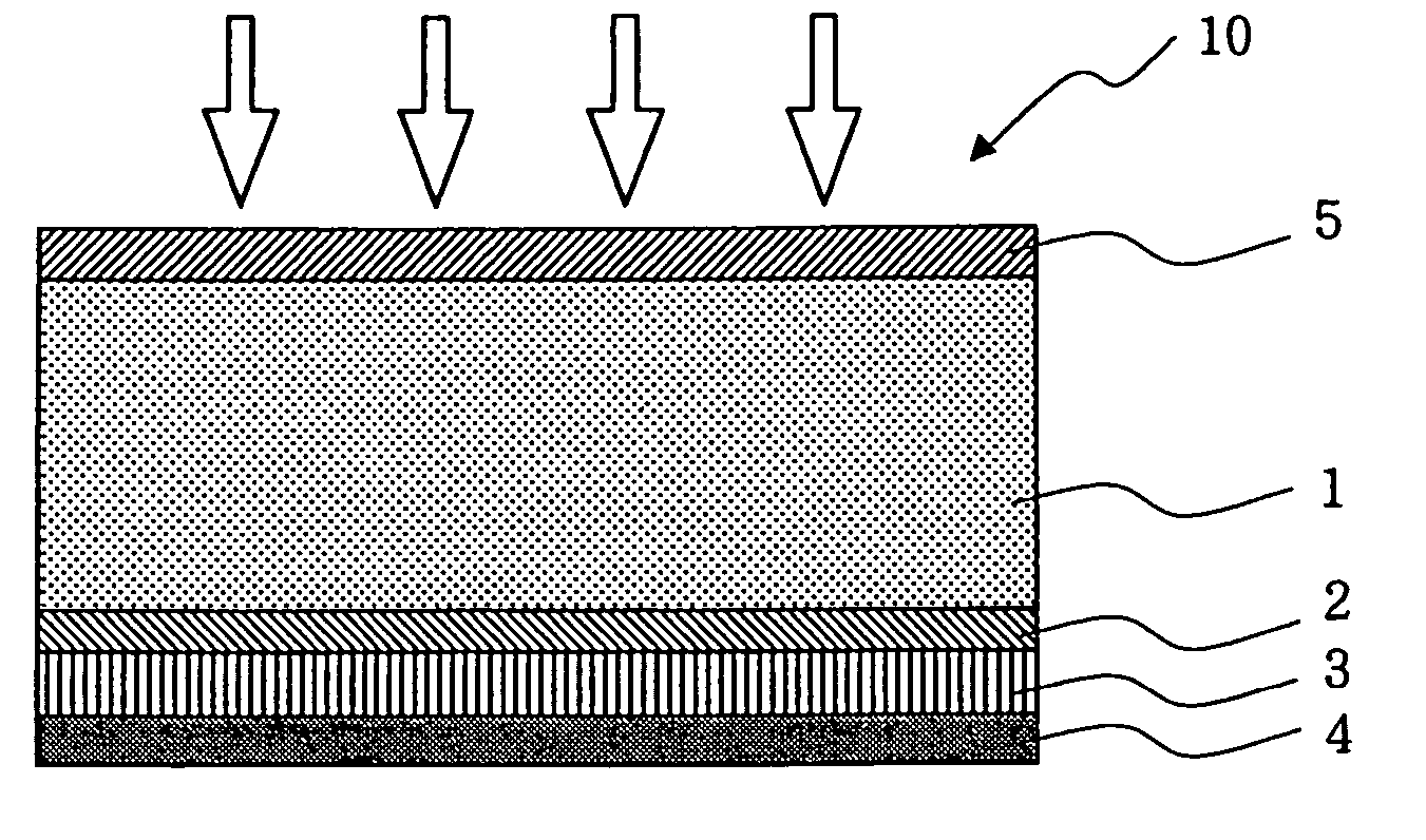
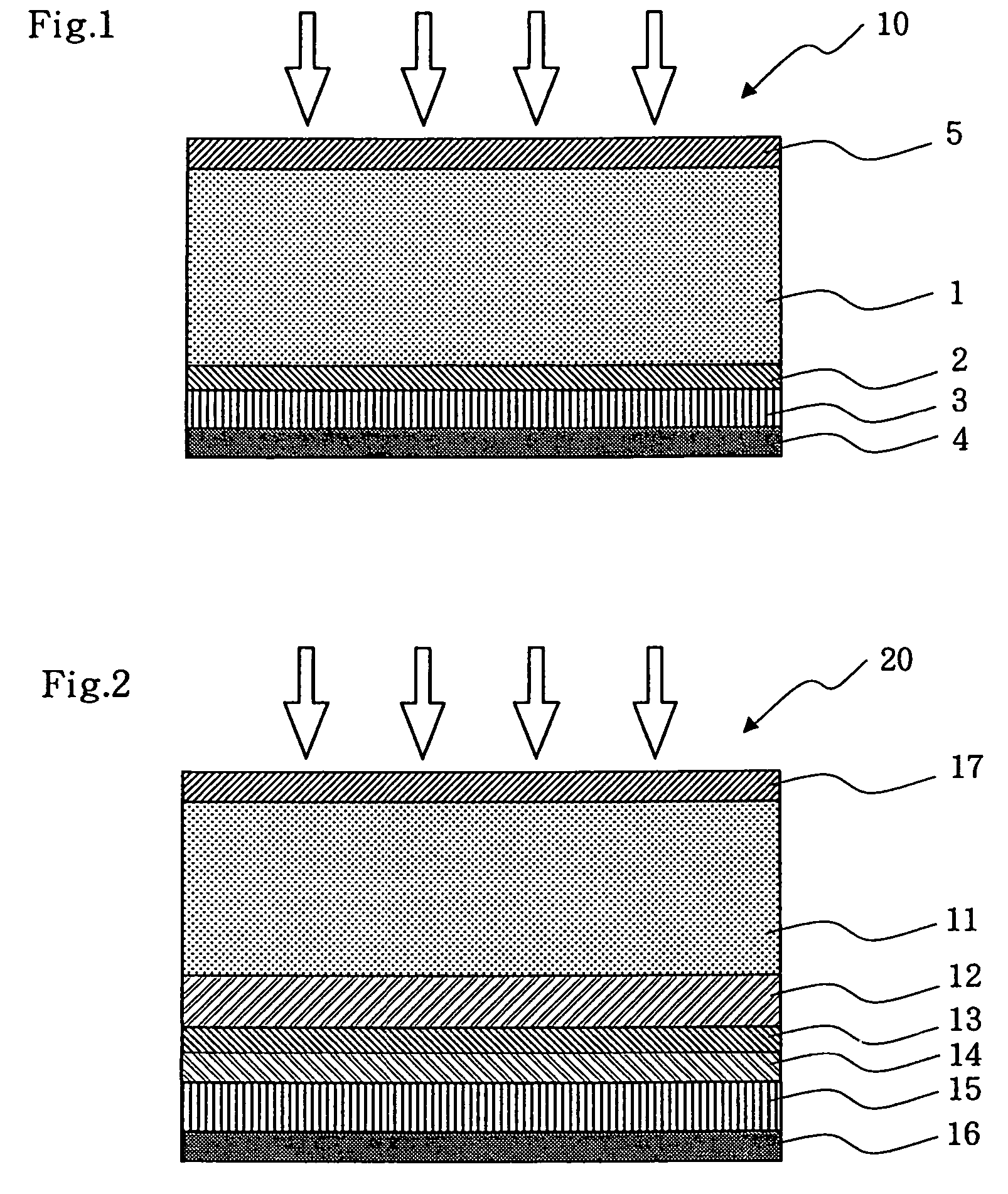
Optical disc and method for manufacturing the same
a technology of optical discs and a manufacturing method, applied in the field of optical discs, can solve the problems of cracks at the surface and residual solvent content, and achieve the effects of excellent high abrasion resistance and scratch resistance, superior storage reliability, and high strength
- Summary
- Abstract
- Description
- Claims
- Application Information
AI Technical Summary
Benefits of technology
Problems solved by technology
Method used
Image

Examples
examples
[0046]Examples of the present invention will now be described in detail.
[0047]A hard coating solution was prepared as follows, which was essentially composed of a UV-curable acrylic resin containing dispersed colloidal silica with a mean particle size of about 10 nm and PGME as the solvent.
[0048]Reactive group-modified colloidal silica: 50 parts by weight
[0049]Dipentaerythritol hexaacrylate: 48 parts by weight
[0050]Tetrahydrofurfuryl acrylate: 12 parts by weight
[0051]PGME (non-reactive solvent): 100 parts by weight
[0052]Irgacure 184 (polymerization initiator, produced by Ciba Specialty Chemicals Inc.): 5 parts by weight To the mixture of these materials, 0.002 part by weight of bifunctional silicone methacrylate (X-22-164A, molecular weight: 1500, produced by Shin-Etsu Chemical Co., Ltd.) was added to yield the hard coating solution. The total solid content was 53.5 percent by weight, and contained 43.5 percent by weight of colloidal silica relative to the total solid content.
[0053]...
PUM
| Property | Measurement | Unit |
|---|---|---|
| thickness | aaaaa | aaaaa |
| mean particle size | aaaaa | aaaaa |
| haze test | aaaaa | aaaaa |
Abstract
Description
Claims
Application Information
 - R&D Engineer
- R&D Manager
- IP Professional
- Industry Leading Data Capabilities
- Powerful AI technology
- Patent DNA Extraction
Browse by: Latest US Patents, China's latest patents, Technical Efficacy Thesaurus, Application Domain, Technology Topic, Popular Technical Reports.
© 2024 PatSnap. All rights reserved.Legal|Privacy policy|Modern Slavery Act Transparency Statement|Sitemap|About US| Contact US: help@patsnap.com