Optical component and method of manufacturing same

a technology of optical components and components, applied in the field of optical components, can solve the problems of difficult use of polarizers, inability to obtain uniform spectral characteristics within a plane, and marked changes in reflection and transmission characteristics, and achieve good polarization characteristics

Inactive Publication Date: 2006-03-07
CANON KK
View PDF15 Cites 40 Cited by
  • Summary
  • Abstract
  • Description
  • Claims
  • Application Information

AI Technical Summary

Benefits of technology

[0013]It is, therefore, an object of the preset invention to provide an optical component that can show good polarization characteristics for a visible light of a wavelength of 400 to 700 nm.
[0014]It is another object of the present invention to stably maintain, during a manufacturing process or practical use, the shape of dielectric multilayer films formed with a fine recess / protrusion shape on a surface of an optical element even when the dielectric multilayer films have a high aspect ratio.
[0015]It is yet another object of the present invention to provide a manufacturing method capable of surely forming such fine recesses and protrusions using an inexpensive manufacturing apparatus without use of any organic solvent.

Problems solved by technology

However, although the cubic type polarizing beam splitter shown in FIG. 5 is very easy to manufacture and has good reproducibility, there is a problem as to its optical characteristics that the reflection and transmission characteristics change markedly depending on the incident angle of light.
However, because the angle at which a light is incident on the polarizing beam splitter varies markedly depending on the position of the incidence, the reflection or transmission characteristics are not constant, thus making it impossible to obtain uniform spectral characteristics within a plane.
However, the polarizer is difficult to use if an incident light to be polarized is a visible light having a wavelength of 400 to 700 nm.
Thus, the polarizer is difficult to use in an optical component such as a liquid crystal projector which must allow a light of a visible range to pass therethrough.
Further, because the difference between the refractive index of TiO2 and TaO2 constituting the high refractive index layer and that of SiO2 constituting the low refractive index layer is too small, sufficient polarization characteristics cannot be obtained.

Method used


Image

  • Optical component and method of manufacturing same
  • Optical component and method of manufacturing same
  • Optical component and method of manufacturing same

Examples


example 1

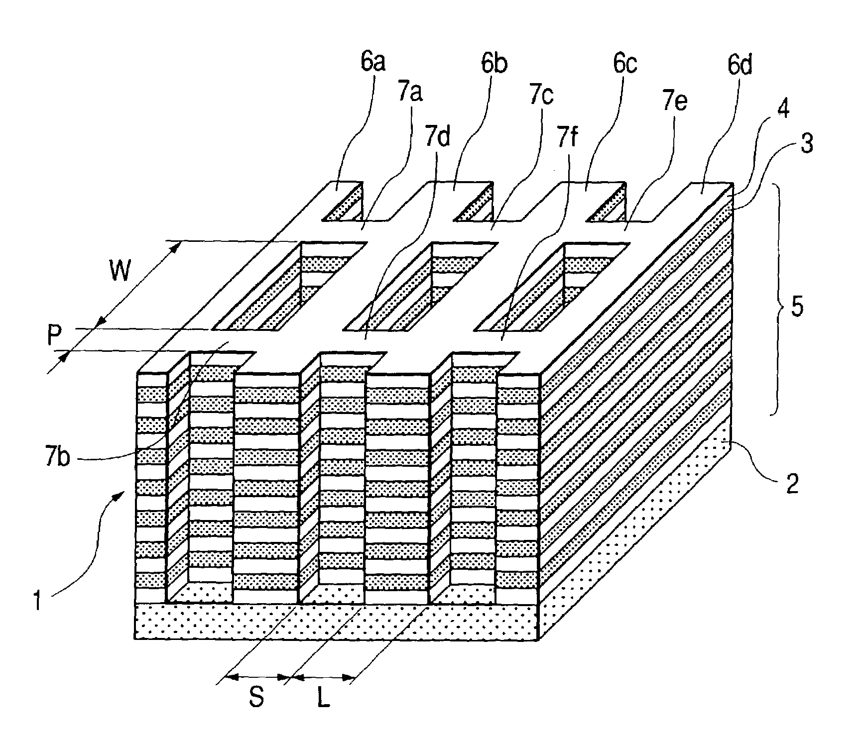
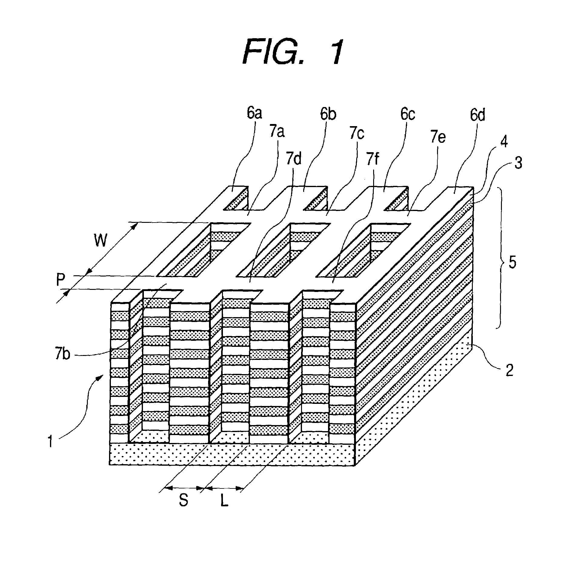
[0061]The polarizing beam splitter 1 shown in FIG. 1 was manufactured, and its characteristics were experimentally investigated. The polarizing beam splitter 1 manufactured was formed of the high refractive index layers 4 of TiO2 and the low refractive index layers 3 of SiO2 alternately stacked on each other on the transparent substrate 2 of quartz which was 30 mm in length, 30 mm in width, and 1 mm in thickness. In this case, the TiO2 layer had a thickness of 68 nm, and the SiO2 layer had a thickness of 118 nm. These values were designed to allow the polarizing beam splitter to provide sufficient functions on the basis of the light beam incident angle of 45°. The lines 6a, 6b, 6c, 6d of the multilayer film each had a width L of 100 nm, and the interval S between the adjacent lines 6a and 6b, 6b and 6c, and 6c and 6d of the multilayer film was 100 nm. Further, the width P of each of the connecting multilayer films 7a, 7b, 7c, 7d, 7e, 7f was 100 nm, and the interval W between the con...


PUM

PropertyMeasurementUnit
aspect ratioaaaaaaaaaa
depthaaaaaaaaaa
depthaaaaaaaaaa

Abstract

A multilayer film having two kinds of films of different refractive indexes alternately stacked on each other on a substrate composed of an optical element is formed in a plurality of parallel lines, and the adjacent lines of the multilayer film are connected to each other by means of a connecting multilayer film to reinforce them. This makes it possible to provide a highly reliable optical component which shows good polarization characteristic even for a visible light of a wavelength of 400 to 700 nm and in which even when designed to have a high aspect ratio, the linear multilayer film will not fall down. There is also provided a manufacturing method that enables a fine recess / protrusion shape to be surely formed using an inexpensive manufacturing apparatus without use of any organic solvent.

Description

BACKGROUND OF THE INVENTION[0001]1. Field of the Invention[0002]The present invention relates to an optical component such as a polarizing beam splitter or a phase plate in which a multilayer film is provided on a surface of a substrate to polarize incident light, and in particular, to an optical component having a multilayer film with a high aspect ratio as well as a method of manufacturing the same.[0003]2. Related Background Art[0004]Hitherto, an optical component such as a lens, used in an electronic equipment is based on an optical interference and has thin layers stacked on a surface of an optical element as an antireflection film. Further, on the basis of a similar optical interference, thin layers are stacked on a surface of a substrate composed of a transparent optical element to polarize an incident light, thereby forming a polarizing beam splitter or a phase plate. Such an interference film is inexpensive and has good reproducibility, and is thus put to practical use wide...

Claims


Application Information

Patent Timeline
Patent Type & Authority Patents(United States)
IPC IPC(8): G02B5/30G02B5/18G03F7/00
CPCG02B5/3025G02B5/1847G02B5/008Y10S359/90G02B5/30
Inventor SAKAMOTO, JUNICHI
Owner CANON KK
Why Eureka
Try Eureka