Rotating electric hand tool implement with safety routine

a technology of electric hand tools and safety routines, which is applied in the direction of portable power-driven tools, percussive tools, drilling machines and methods, etc., can solve the problems of excessive rotation of the housing, high danger of injury, and injuring the operator, so as to achieve simple separation of power transmission and reliably prevent an excessively high twisting of the housing

Inactive Publication Date: 2006-03-14
HILTI AG
View PDF12 Cites 36 Cited by
  • Summary
  • Abstract
  • Description
  • Claims
  • Application Information

AI Technical Summary

Benefits of technology

[0007]It is primary object of the invention to provide a simple separation of the transmission of power in the case of electric hand tool appa

Problems solved by technology

In the case of large, high-powered, rotating, electric hand tool apparatus, the danger exists of injuring the operator by means of excessive rotation of the housing as the latter is carried along due to the sudden obstruction of the tool as a consequence of the kinetic energy stored in the electric hand tool apparatus.
The danger of injury is particularly high if the apparatus is obstructed as it is started, that is, if the tool is obstructed when it is initially switched on.
Usually, the sudden high angular momentum, producing this rotation due to the obstruction, is separated from the blocked tool by slip clutches or safety clutches or is limited with respect to the torque.
Frequently, however, the separation is delayed so that, due to the rotational energy alr

Method used


Image

  • Rotating electric hand tool implement with safety routine
  • Rotating electric hand tool implement with safety routine

Examples


Embodiment Construction

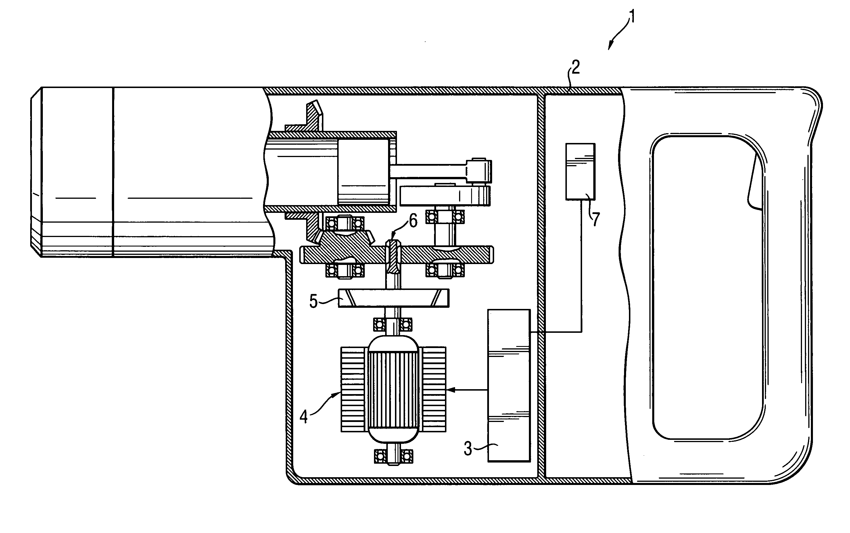
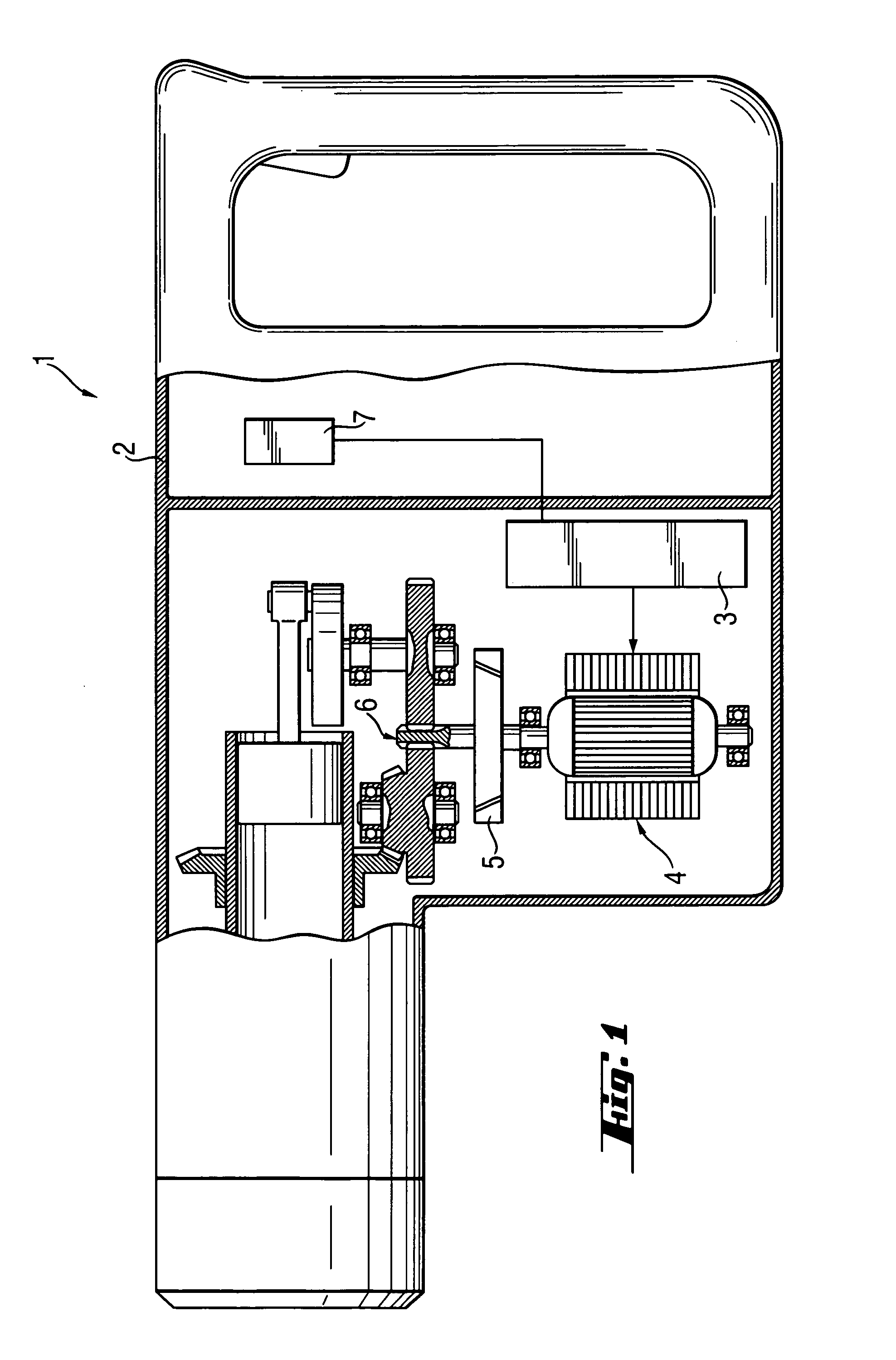
[0013]According to FIG. 1, a hammerdrill electric hand tool apparatus 1 has within a housing 2, an electric motor 4 without or free of a collector and slip ring, and the rpm of which can be controlled by motor control electronics 3, especially a switched magnetic reluctance motor, which is connected, for transfer driving power over a force transfer path containing a strictly mechanical, rpm-dependent clutch 5 to a transmission 6. Moreover, the housing 2 is connected with a sensor 7, which is evaluated by a microcontroller, for determining a future, excessively high twisting of the housing 2.

[0014]The method for limiting an excessively high twisting of the housing in the event of an obstruction of the apparatus comprises[0015]in a first step, in the event of an excessively high twisting, recorded by the microcontroller with sensor and to be expected in the future, the triggering of a safety signal by the microcontroller,[0016]in a second step, the slowing down of the rpm of the rpm-c...


PUM

PropertyMeasurementUnit
Forceaaaaaaaaaa

Abstract

An electric hand tool apparatus (1) for driving a drill-like tool, which carries out an at least partial rotational movement, has within a housing (2), an electric motor (4) without or free of collector and slip ring, the rpm of which can be controlled by motor control electronics (3), wherein an rpm-dependent clutch (5) for transferring the torque is disposed in a force transfer path from the electric motor (4) to a transmission (6). Optionally, to prevent an excessively high twisting of the housing (2), a sensor (7) is evaluated and the rpm of the electric motor (4) is reduced in order to sever the transfer of force by the rpm-dependent clutch (5).

Description

BACKGROUND OF THE INVENTION[0001]The invention relates to a coordinated, rotating, electric hand tool apparatus, particularly a drill, a hammerdrill or a combination hammer, and to a method of safe operation thereof.[0002]In the case of large, high-powered, rotating, electric hand tool apparatus, the danger exists of injuring the operator by means of excessive rotation of the housing as the latter is carried along due to the sudden obstruction of the tool as a consequence of the kinetic energy stored in the electric hand tool apparatus. The danger of injury is particularly high if the apparatus is obstructed as it is started, that is, if the tool is obstructed when it is initially switched on.[0003]Usually, the sudden high angular momentum, producing this rotation due to the obstruction, is separated from the blocked tool by slip clutches or safety clutches or is limited with respect to the torque. Frequently, however, the separation is delayed so that, due to the rotational energy ...

Claims


Application Information

Patent Timeline
IPC IPC(8): B25D13/00B25D16/00B23B45/00B23B45/16B25F5/00F16D43/04
CPCB25F5/00
Inventor KRISTEN, FERDINANDBONGERS-AMBROSIUS, HANS-WERNER
Owner HILTI AG
Why Eureka
Try Eureka