Automatic parameter estimation extension for variable speed pumps

Active Publication Date: 2006-03-14
BENTLEY SYST INC
View PDF5 Cites 8 Cited by
  • Summary
  • Abstract
  • Description
  • Claims
  • Application Information

AI Technical Summary

Benefits of technology

[0019]In accordance with another aspect of the present invention, the method of the present invention can be readily emp

Problems solved by technology

This matrix is largely symmetrical, however, certain aspects of the system (representing the variable speed pump, i

Method used


Image

  • Automatic parameter estimation extension for variable speed pumps
  • Automatic parameter estimation extension for variable speed pumps
  • Automatic parameter estimation extension for variable speed pumps

Examples


Embodiment Construction

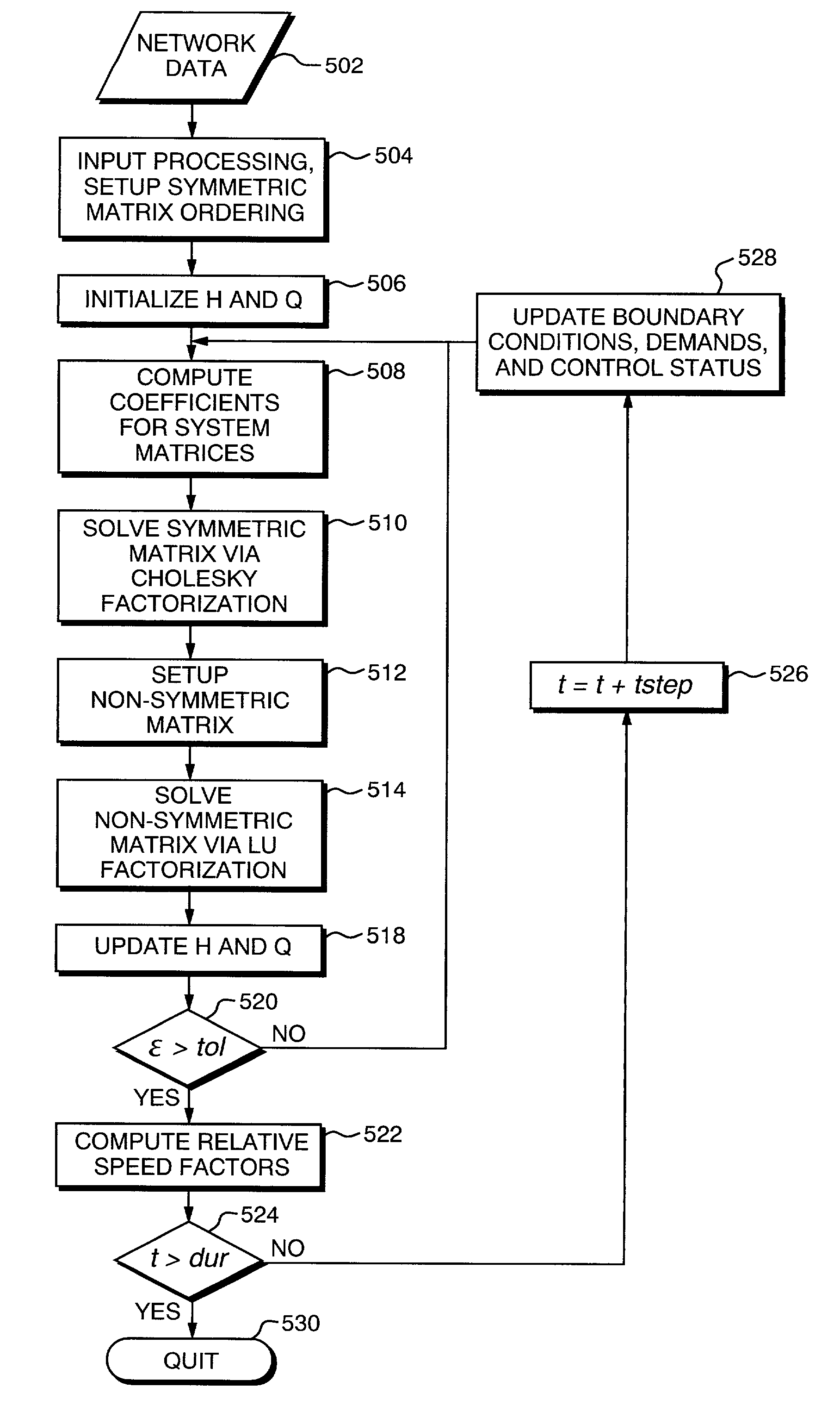
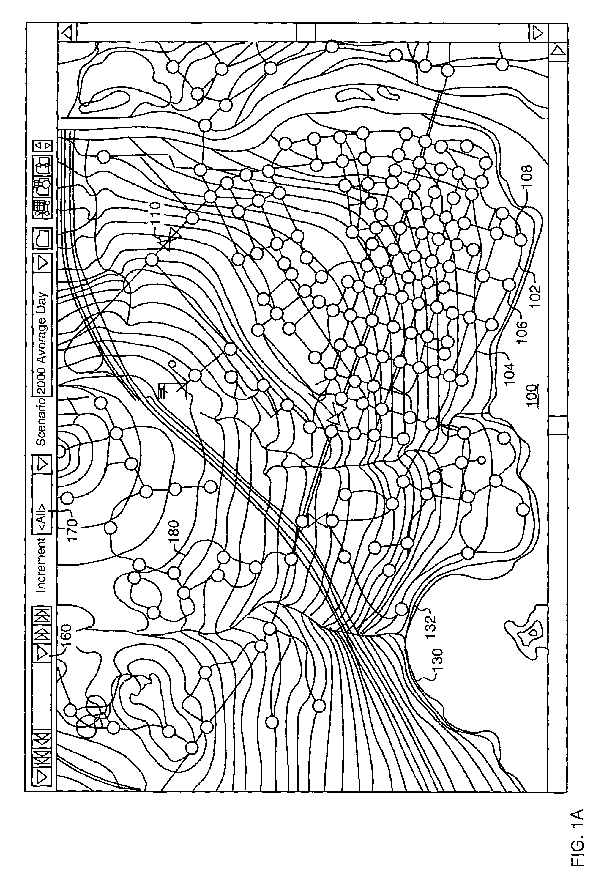
[0027]Hydraulic systems can be designed and described using hydraulic network solver software, that employs a hydraulic calculation engine. This software is used to solve flow continuity and head loss equations that characterize the hydraulic state of the pipe network at a given point in time. A user interface of a hydraulic network solver software program is illustrated in FIG. 1A. In FIG. 1A, the hydraulic network 100 is made up of a series of links (also referred to herein as pipes) such as the pipes 102, 104. The pipes are connected at nodes (also referred to herein as junctions), such as the junctions 106, 108. The network 100 may also include valves such as the valve 110 and variable speed pumps such as the variable speed pump 112. The multiple isometric lines, such as the lines 130, 132, upon which the network 100 is superimposed, are topological lines that illustrate the geography of the area in which the hydraulic network 100 is located.

[0028]As noted, flow continuity and h...


PUM


Abstract

A method for estimating the relative speed factor parameter for a variable speed pump in a hydraulic network sufficient to maintain a fixed pressure at a control node is provided. A desired operating characteristic is determined and this is inserted into a matrix of equations describing the hydraulic system. The largely symmetrical matrix includes certain aspects of the system representing the variable speed pumps which are non-symmetrical. Non-symmetrical portions of the matrix are separated out and solved using an LU factorization technique. Non-sparse, non symmetric matrices are generated and the difference in head correction is solved for to compute the updated nodal head vector and ultimately determine the variable pump speed parameter. The invention allows estimation of the variable speed factor for a variable speed pump drive sufficient to maintain a fixed pressure at a control node. The system fully integrates variable pump speed operation with the status and control capabilities of known hydraulic network solvers.

Description

BACKGROUND OF THE INVENTION[0001]1. Field of the Invention[0002]This invention relates to the design and analysis of water distribution systems and particularly, to variable speed pumps used in such designs.[0003]2. Background Information[0004]In many civil engineering applications, and in particular, in water distribution networks for cities, townships and municipalities, it is of the utmost importance to design such systems accurately and to predict water pipe flow and hydraulic pressure conditions for the water network in any particular area. This is to design, build, maintain, and operate water infrastructure efficiently and to ensure the availability of the potable water resource to the community.[0005]Water distribution systems are often described using software for this purpose. A hydraulic network solver (often commonly referred to as a “solver”) is a computer program that simulates and predicts water pipe flow and hydraulic pressure conditions for the links (such as pipes) ...

Claims


Application Information

Patent Timeline
IPC IPC(8): G06G7/48
CPCG05B15/02
Inventor TODINI, EZIOTRYBY, MICHAEL E.COOK, JACK S.WALSKI, THOMAS M.MANKOWSKI, ROBERT F.
Owner BENTLEY SYST INC
Why Eureka
Try Eureka