Method and device for cutting flat work pieces made of a brittle material

a flat work piece and material technology, applied in the direction of stone-like material working apparatus, glass making apparatus, laser beam welding apparatus, etc., can solve the problems of uneven glass edge, reduced mechanical stressability, particle release from surface, etc., and achieve the effect of relatively easy freeform cutting

Inactive Publication Date: 2006-03-21
SCHOTT AG
View PDF8 Cites 29 Cited by
  • Summary
  • Abstract
  • Description
  • Claims
  • Application Information

AI Technical Summary

Benefits of technology

[0010]The invention is based on the object of carrying out the method described initially in such a fashion, and of designing the associated device in such a fashion that freeform cuts can be accomplished relatively easily using the laser beam separating method.

Problems solved by technology

The disadvantage of this method is that the scribed line causes particles (fragments) to be released from the surface, which said particles can deposit on the glass and scratch it, for example.
Additionally, “chips” can be created in the cut edge, which results in an uneven glass edge.
Furthermore, the micro-cracks produced in the cut edge during the scribing process lead to reduced mechanical stressability, i.e., to increased risk of breakage.
In this approach, a heat source directed at the glass is moved at a fixed speed relative to the glass, thereby producing such a high thermal mechanical tension that cracks form in the glass.
As a result, the glass can first be scribed using the laser beam and then broken mechanically.
This would require, in particular, coupling the scanner device producing the respective two-dimensional focal point plus the cold spot device to a trajectory control device, the realization of which is very problematic due to the large quantities of data to be exchanged and the cutting speeds required.
This method is greatly restricted as well in terms of its usability.

Method used


Image

  • Method and device for cutting flat work pieces made of a brittle material
  • Method and device for cutting flat work pieces made of a brittle material
  • Method and device for cutting flat work pieces made of a brittle material

Examples


Embodiment Construction

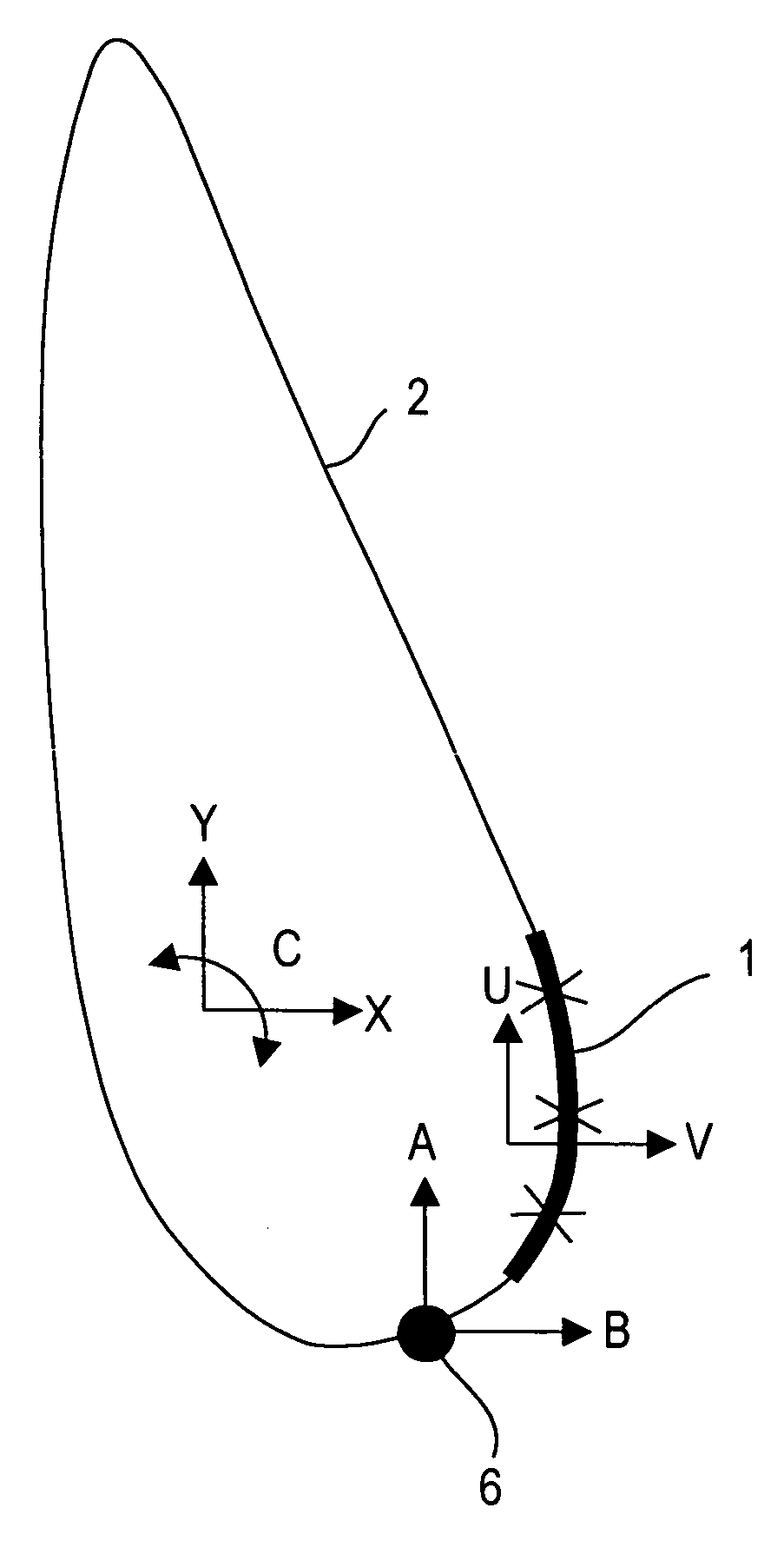
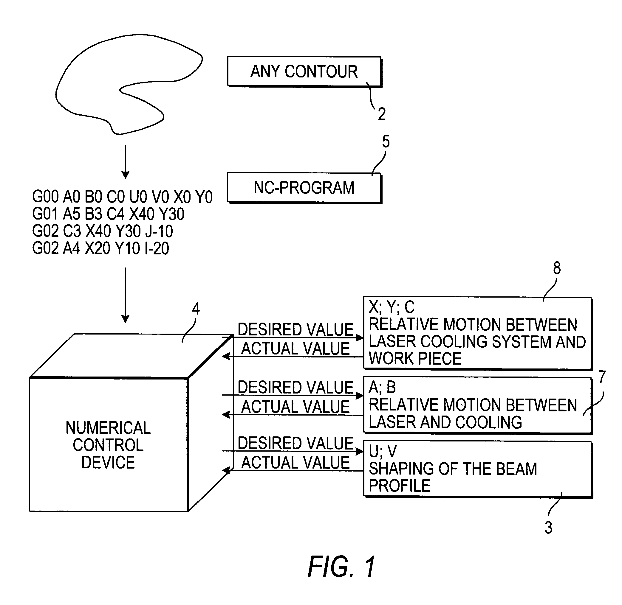
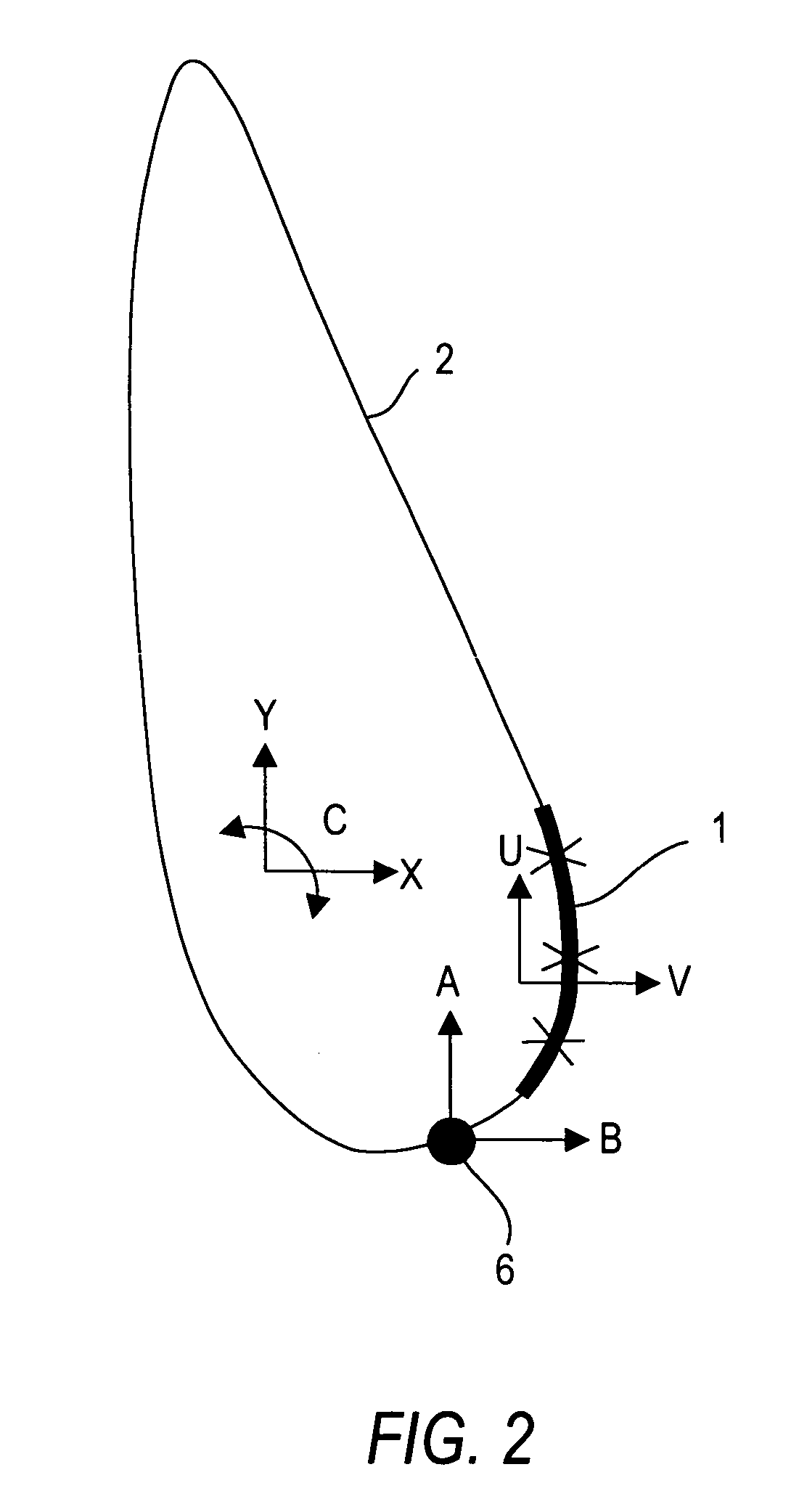
[0022]The principle according to the invention for cutting a flat work piece made of a brittle material, in particular flat glasses, using the laser beam separating method is shown in FIGS. 1 and 2. FIG. 1 shows the principle layout of the control of the sequences of motions along a specified contour. FIG. 2 shows the focal point geometry of the laser beam with the cold spot following it, and the matching of the axes of motion to the contour controller according to FIG. 1.

[0023]The separating principle according to the invention is based on a linear focal point 1 that is curved in accordance with the respective contour of the dividing line 2. If the dividing line 2 is linear, the focal line 1 can be relatively long, as shown in FIG. 3. The smaller the radius of curvature of the contour of the dividing line 2 is, the shorter the line 1 must be, so that the main application of energy takes place on the dividing line. The line length varies hereby between 10 mm and 100 mm. In parallel ...


PUM

PropertyMeasurementUnit
lengthaaaaaaaaaa
lengthaaaaaaaaaa
oscillation frequencyaaaaaaaaaa

Abstract

The apparatus for cutting a flat glass work piece along a curved dividing line includes a laser generating a laser beam having a linear beam profile and an optical system with a scanner for producing a curvilinear focal point from the laser beam. The apparatus also moves a cold spot along the curved dividing line following the curvilinear focal point. A trajectory control device controls the position of the curvilinear focal point on the curved dividing line via actuators. A profile control device controls the contour of the curvilinear focal point according to trajectory data from the curved dividing line, so that all points of the curvilinear focal point lie on or coincide with the curved dividing line. The apparatus adjusts the length of the curvilinear focal point by adjusting scanning amplitude of the scanning motion.

Description

CROSS-REFERENCE[0001]This is a divisional of U.S. patent application, Ser. No. 10 / 149,781, filed Jun. 13, 2002, which has now been allowed as U.S. Pat. No. 6,811,069, which is a 371 of PCT / EP00 / 12460, filed Dec. 09, 2000.DESCRIPTION[0002]The invention is based on a method for cutting flat work pieces made of a brittle material, in particular glass or ceramic, in which a laser beam having a linear beam profile followed by a cold spot is moved along a dividing line having a specified contour. A preferred application of the method is in the cutting of flat glasses.[0003]The invention is based further on a device for cutting a work piece of this type using a laser beam in the form of a linear beam profile followed by a cold spot.[0004]Conventional methods for cutting flat glasses are based on the use of a diamond or a small rotary cutter to first produce a scribed line in the glass in order to then break the glass by application of an external mechanical force along the weak point produ...

Claims


Application Information

Patent Timeline
Patent Type & Authority Patents(United States)
IPC IPC(8): B23K26/38B28D1/00B23K26/00B23K26/073B23K26/08B23K26/082B23K26/364B23K26/40C03B33/04C03B33/09
CPCB23K26/073B23K26/0738B23K26/08C03B33/091B23K26/367B23K26/4075C03B33/04B23K26/0807B23K26/364B23K26/082B23K26/40B23K2103/50Y10T225/12Y10T225/304
Inventor HAUER, DIRKHOETZEL, BERNDT
Owner SCHOTT AG
Why Eureka
Try Eureka