Motor drive control

Active Publication Date: 2006-03-21
TRW LIMITED
View PDF9 Cites 56 Cited by
  • Summary
  • Abstract
  • Description
  • Claims
  • Application Information

AI Technical Summary

Benefits of technology

[0022]Preferably the control means is arranged to provide a first PWM pattern in a first PWM period to allow inductance measurement of at least one phase and a second, different PWM pattern in a second PWM period to allow inductance measurement of at least one phase not measured in the first PWM period, and to produce at least one intermediate PWM pattern in a PWM period between the first and second periods, the intermediate pattern being intermediate in shape between the first and second patterns. This can help to reduce acoustic noise. The control means may need to be arranged not to measure the inductance of the phases in the intermediate PWM period.

Problems solved by technology

However, these algorithms cannot detect the position down to zero speed because there is no back emf to detect at zero speed.
Since the injected voltage signal does not produce useful motive torque, it reduces the maximum “useful” voltage at the windings.
Obviously with this technique, it is not possible to measure all three inductances simultaneously.
One problem is that because the inductances are not sampled simultaneously, there is some error introduced into the position measurement.
This error will be exacerbated if either the d- or q-axis inductances change rapidly with operating conditions, which could be the case with certain types of buried magnet motors.
The delay between the measurements also introduces further time delays into the position response of the system.
This reduces the dynamic capability of the drive, which can be a problem, particularly in a servo-drive system.
The biggest problem with this approach is the generation of acoustic noise.
Practical demonstrations of such a system suggest that as it stands this noise would be unacceptable for most automotive applications.

Method used


Image

  • Motor drive control
  • Motor drive control
  • Motor drive control

Examples


Embodiment Construction

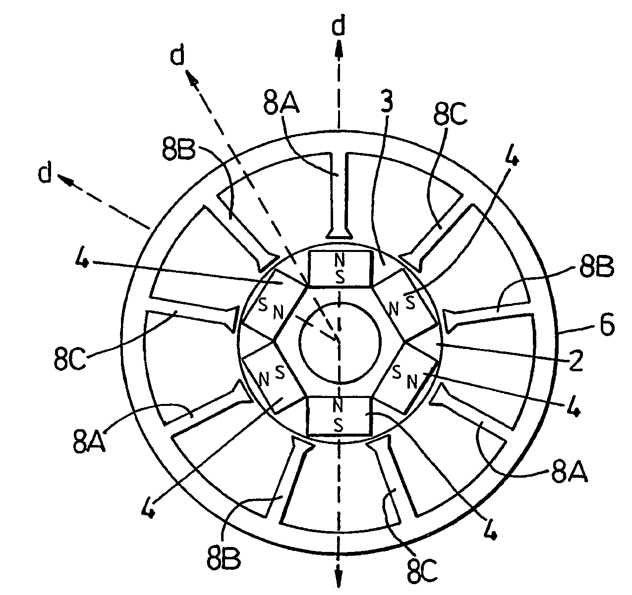
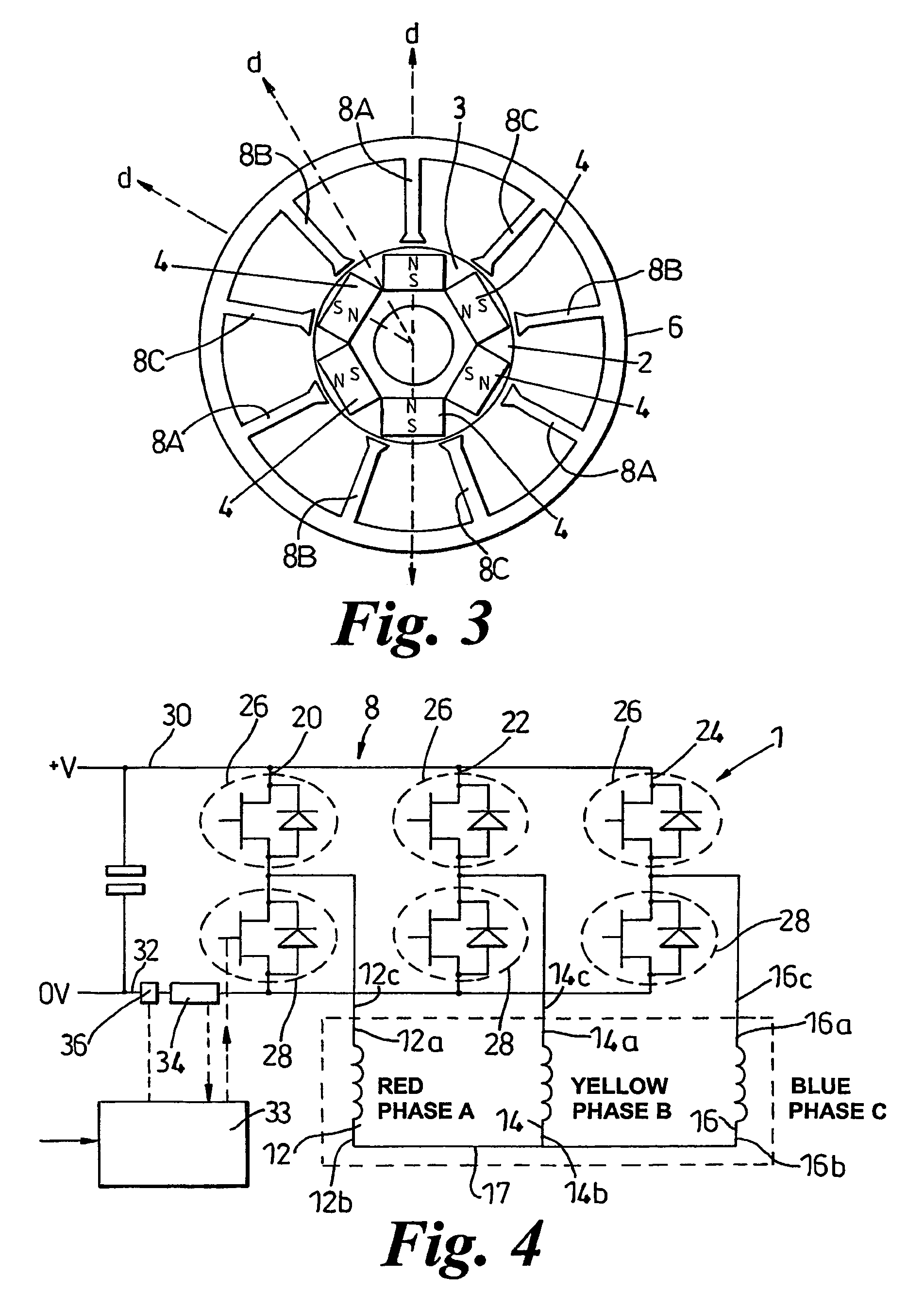
[0057]Referring to FIG. 3 a three phase brushless motor 1 by way of example is provided which comprises a rotor 2 having for example six embedded magnets 4 within it which in this instance are arranged so as to provide six poles which alternate between north and south around the rotor. The rotor therefore defines three direct or d axes evenly spaced around the rotor and three quadrature or q axes interspaced between the d axes. The d axes are aligned with the magnetic poles of the magnets 4 where the lines of magnetic flux from the rotor are in the radial direction, and the q axes are spaced between the d axes where the lines of magnetic flux from the rotor are in the tangential direction.

[0058]A stator 6 comprises a nine slot copper wound element having three groups of three teeth 8A, 8B, 8C each group of teeth having a common winding forming a respective phase. There are therefore three electrical cycles in each full rotation of the rotor, and the three teeth 8A, 8B, 8C in any pha...


PUM


Abstract

A drive system for a three phase brushless motor uses an algorithm for position sensing which measures the inductance in the motor phases and determines the position from the measured inductances. In order to reduce acoustic noise, the inductances are measured during test periods Tsd, which are conducting states added to the PWM pattern in each PWM period. The test periods have net voltage of zero and therefore do not affect the output of the motor, but are sufficiently long to allow inductance measuring as well as the use of a single current sensor for current sensing.

Description

CROSS-REFERENCE TO RELATED APPLICATIONS[0001]This application is a continuation of International Application No. PCT / GB2003 / 003817 filed Sep. 3, 2003, the disclosures of which are incorporated herein by reference, and Great Britain Application No. 0220401.4 filed Sep. 3, 2002, the disclosures of which are incorporated herein by reference.BACKGROUND OF THE INVENTION[0002]This invention relates to electric motor control, and in particular to pulse width modulation (PWM) control of multiple phase brushless motors.[0003]In order to control an electric motor it is necessary to determine the position of the rotor as it rotates relative to the stator, so that the current through the motor windings can be controlled to produce the desired torque. This can be achieved using a dedicated position sensor, or by estimating the position from other parameters using a position sensorless control scheme.[0004]Position sensorless control schemes reduce system costs by replacing the position sensor th...

Claims


Application Information

Patent Timeline
IPC IPC(8): H02P3/18H02P6/16H02P6/18H02P7/06
CPCH02P6/185H02P6/18H02P21/00
Inventor COLES, JEFFREY RONALDWILLIAMS, CONNEL
Owner TRW LIMITED
Why Eureka
Try Eureka