
Spread-spectrum clock generator using processing in the bitstream domain

a clock generator and bitstream technology, applied in the field of clock circuits, can solve problems such as disturbance in the functioning of other electronic devices, and achieve the effect of convenient control

Inactive Publication Date: 2006-03-21
LAPIS SEMICON CO LTD
View PDF5 Cites 26 Cited by
  • Summary
  • Abstract
  • Description
  • Claims
  • Application Information

AI Technical Summary

Benefits of technology

The present invention provides a circuit that can easily control the frequency and amplitude of a modulation signal to reduce EMI (electromagnetic interference) in a PLL-based generated clock signal. The circuit includes a set of input terminals for receiving modulation frequency control inputs, a set of input terminals for receiving dither control signals, and a set of input terminals for receiving frequency deviation control inputs. The circuit also includes a phase detector, a charge pump, a loop filter, a voltage-controlled oscillator, a modulation frequency generator circuit, a modulation sequence generator circuit, a bitstream processor, and a multiplexer circuit. The technical effect of this invention is that it allows for better control over the frequency and amplitude of a modulation signal, which can help reduce EMI in a clock signal.

Problems solved by technology

In certain situations, the energy of the high frequency harmonics can be large enough to cause disturbance in the functioning of other electronic devices through electromagnetic interference (EMI).

Method used


Image

  • Spread-spectrum clock generator using processing in the bitstream domain
  • Spread-spectrum clock generator using processing in the bitstream domain
  • Spread-spectrum clock generator using processing in the bitstream domain

Examples


Embodiment Construction

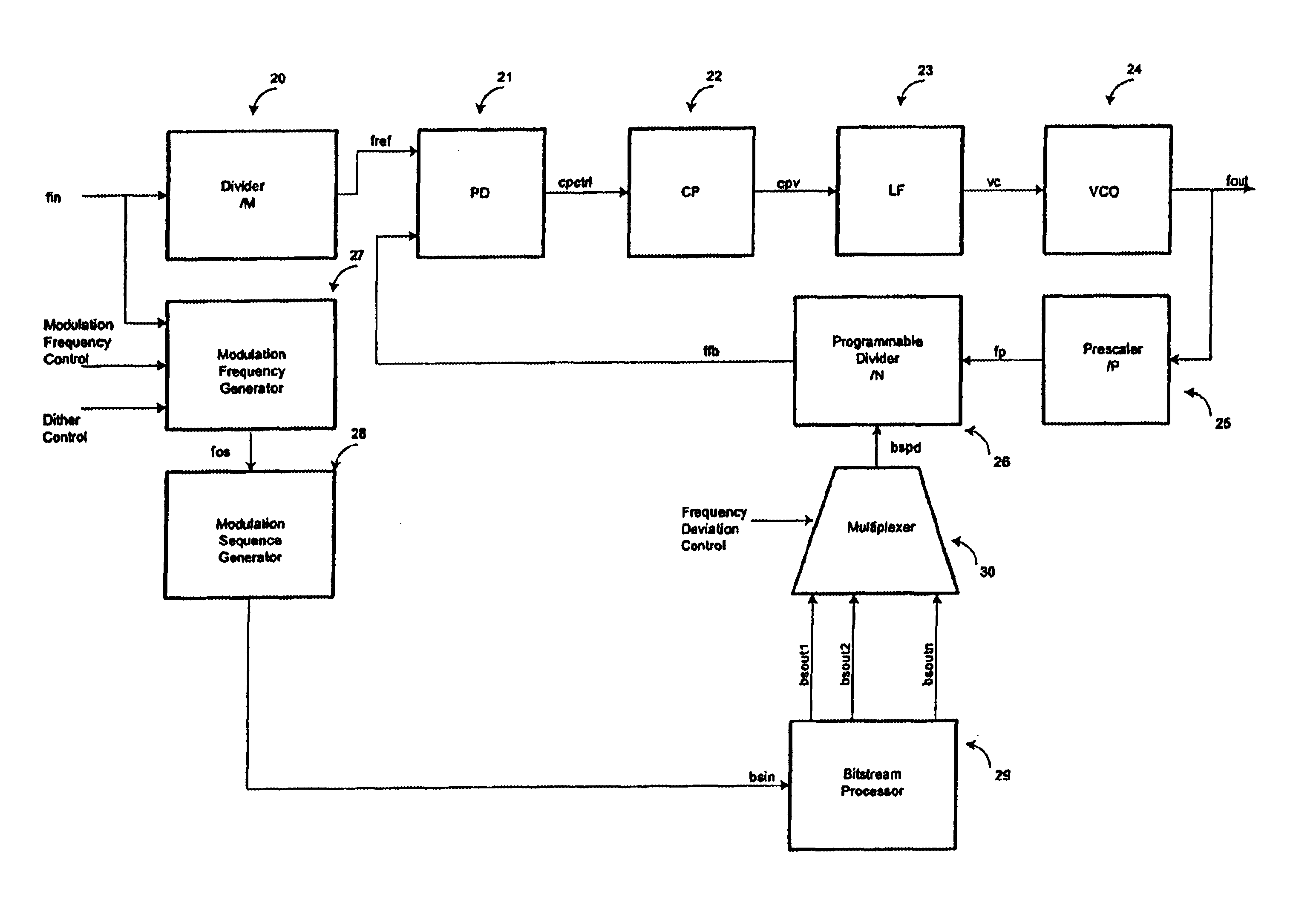
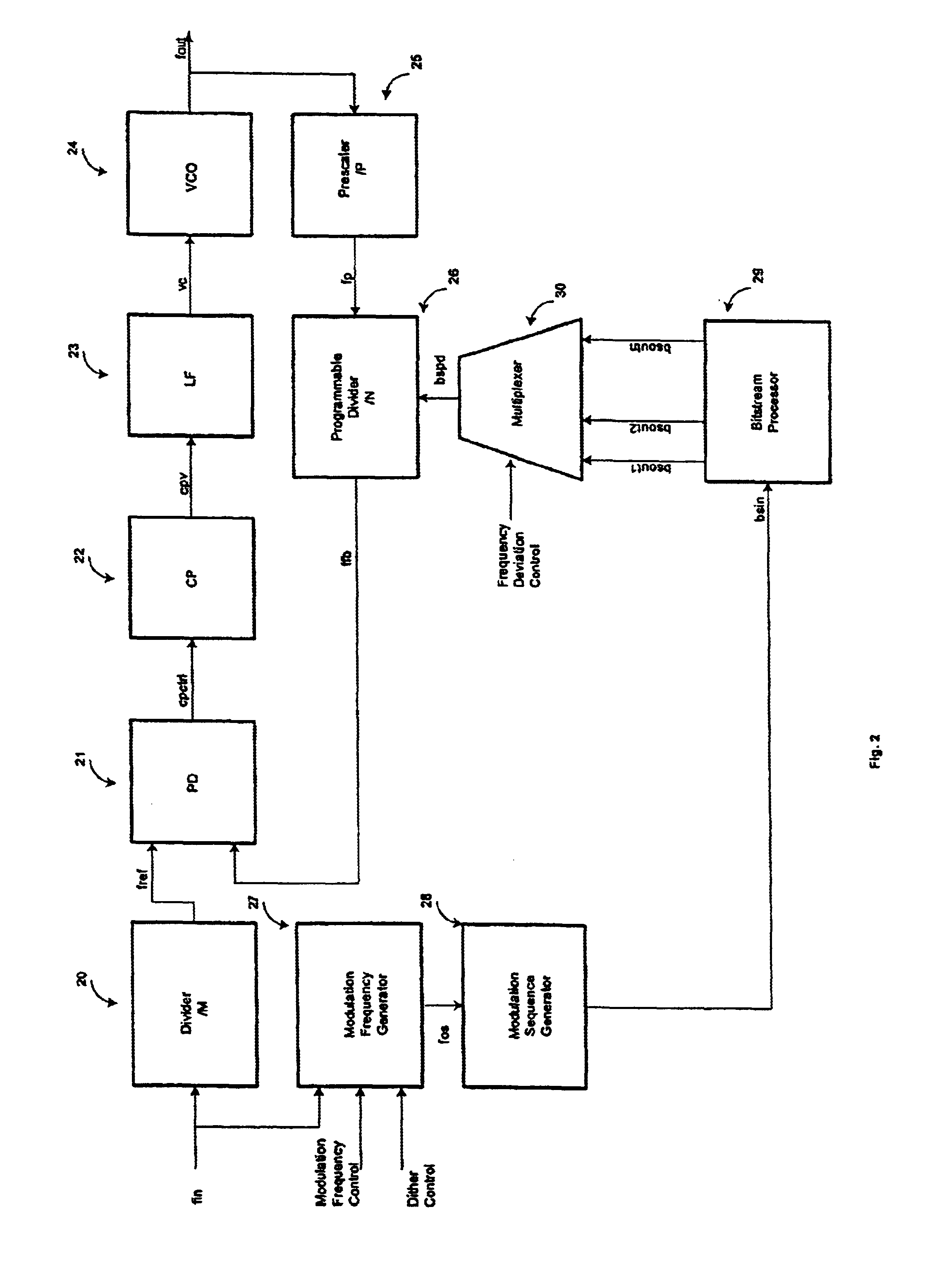
[0020]FIG. 2 shows a block diagram of a PLL-based spread-spectrum clock generating circuit according to the present invention.

[0021]At a first input terminal, the circuit receives a signal with the frequency fin connected to an input of the input divider circuit 20 and to an input of the modulation frequency generator 27. The input divider circuit 20 generates an output signal at the reference frequency fref equal to the input frequency divided by a first integer M:

fref=fin / M.

[0022]The output of the input divider (signal fref) is connected to a first input of the phase detector 21. The output of the phase detector 21 (signal cpctr1) is connected to the input of a charge-pump circuit 22. The output of the charge pump (signal cpv) is connected to the input of a loop filter 23. The loop filter output (signal vc) is connected to the control input of the voltage-controlled oscillator (VCO) 24. The output node of the VCO is tied to an external output terminal and to the internal prescale...


PUM


Abstract

A spread-spectrum phase-locked loop clock generator includes a PLL circuit, a modulation generator, a bit stream processor and a multiplexer. The modulation generator outputs a bitstream in response to an input signal and a control signal. The bitstream processor generates bitstream signals. The multiplexer outputs one of the bitstream signals in response to a frequency deviation control signal. The PLL circuit is controlled by the output of the multiplexer.

Description

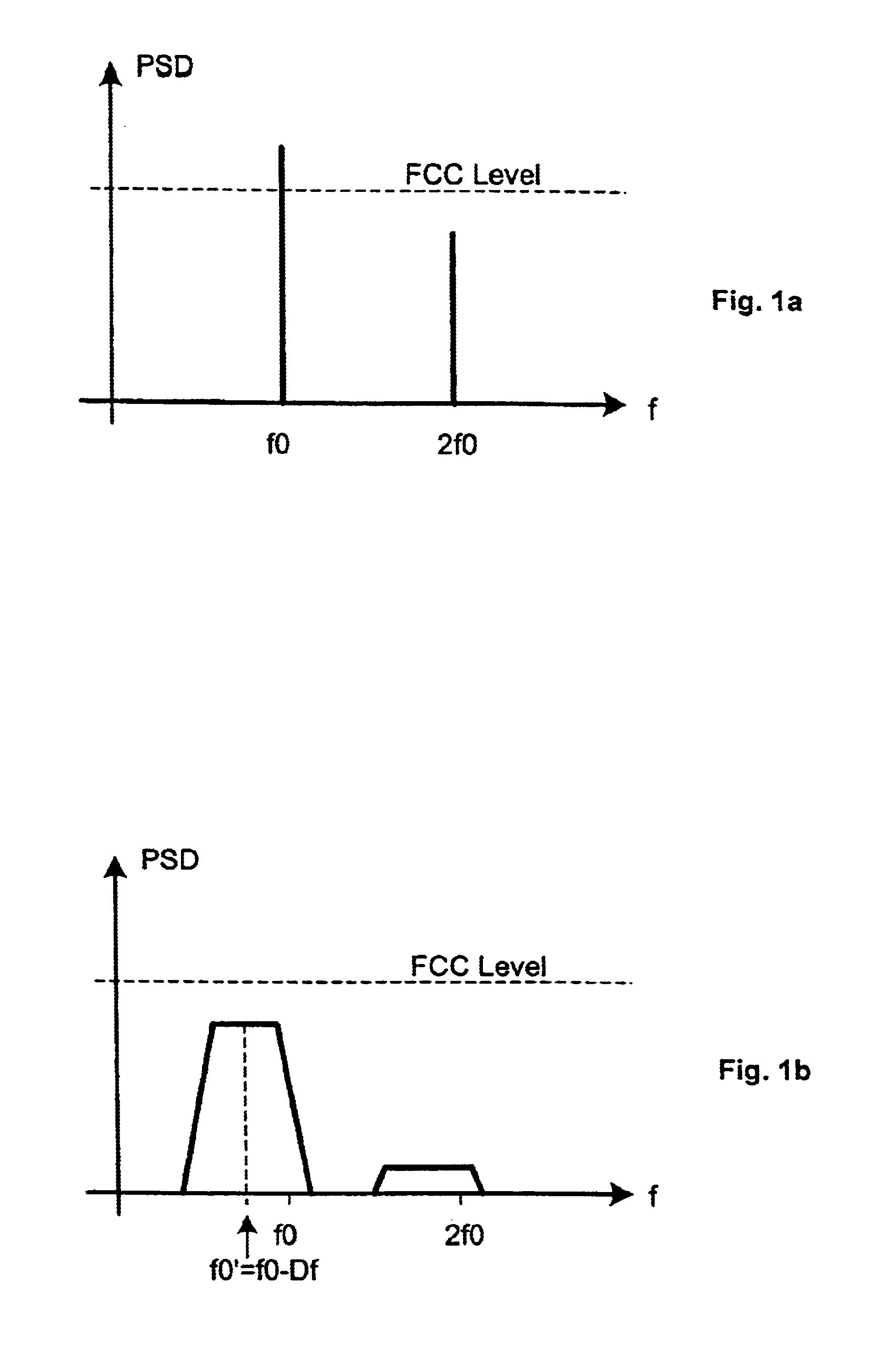
BACKGROUND OF THE INVENTION[0001]The present invention relates to clock circuits and more particularly to a spread-spectrum phase-locked loop clock generator.[0002]The functioning of a large class of electronic devices is governed by clock signals providing means for timing. Some electronic devices make use of high frequency clock signals, usually generated by multiplying through a frequency synthesizer a reference frequency coming from a high stability crystal-controlled oscillator.[0003]The clock signals are, ideally, rectangular in shape, having energy concentrated at the fundamental frequency and at the integer multiples (harmonics) of this fundamental frequency (as shown in FIG. 1a). In certain situations, the energy of the high frequency harmonics can be large enough to cause disturbance in the functioning of other electronic devices through electromagnetic interference (EMI). The level of accepted electromagnetic interference is regulated by the Federal Communications Commiss...

Claims


Application Information

Patent Timeline
Patent Type & Authority Patents(United States)
IPC IPC(8): H03L7/06H03L7/197
CPCH03L7/1976H03L7/197
Inventor GIUROIU, HORIA
Owner LAPIS SEMICON CO LTD
Learn More