Communication with non-flickering illumination

a technology of communication and illumination, applied in the field of communication with non-flickering illumination, can solve the problems of control codes and start codes, too, and achieve the effect of maximizing efficiency

Inactive Publication Date: 2006-03-21
SIGNIFY HLDG BV
View PDF2 Cites 95 Cited by
  • Summary
  • Abstract
  • Description
  • Claims
  • Application Information

AI Technical Summary

Benefits of technology

[0069]In another embodiment, the inverter circuit could be energized directly by a DC or low frequency alternating power source, eliminating the need for a rectifier circuit. This mode of operation is particularly attractive in environments, e.g., automobiles or other transportation systems, where DC power is available a priori Again, the inverter circuit includes special means to vary the frequency...

Problems solved by technology

The data must be analyzed and a proper coding method select...

Method used


Image

  • Communication with non-flickering illumination
  • Communication with non-flickering illumination
  • Communication with non-flickering illumination

Examples


Embodiment Construction

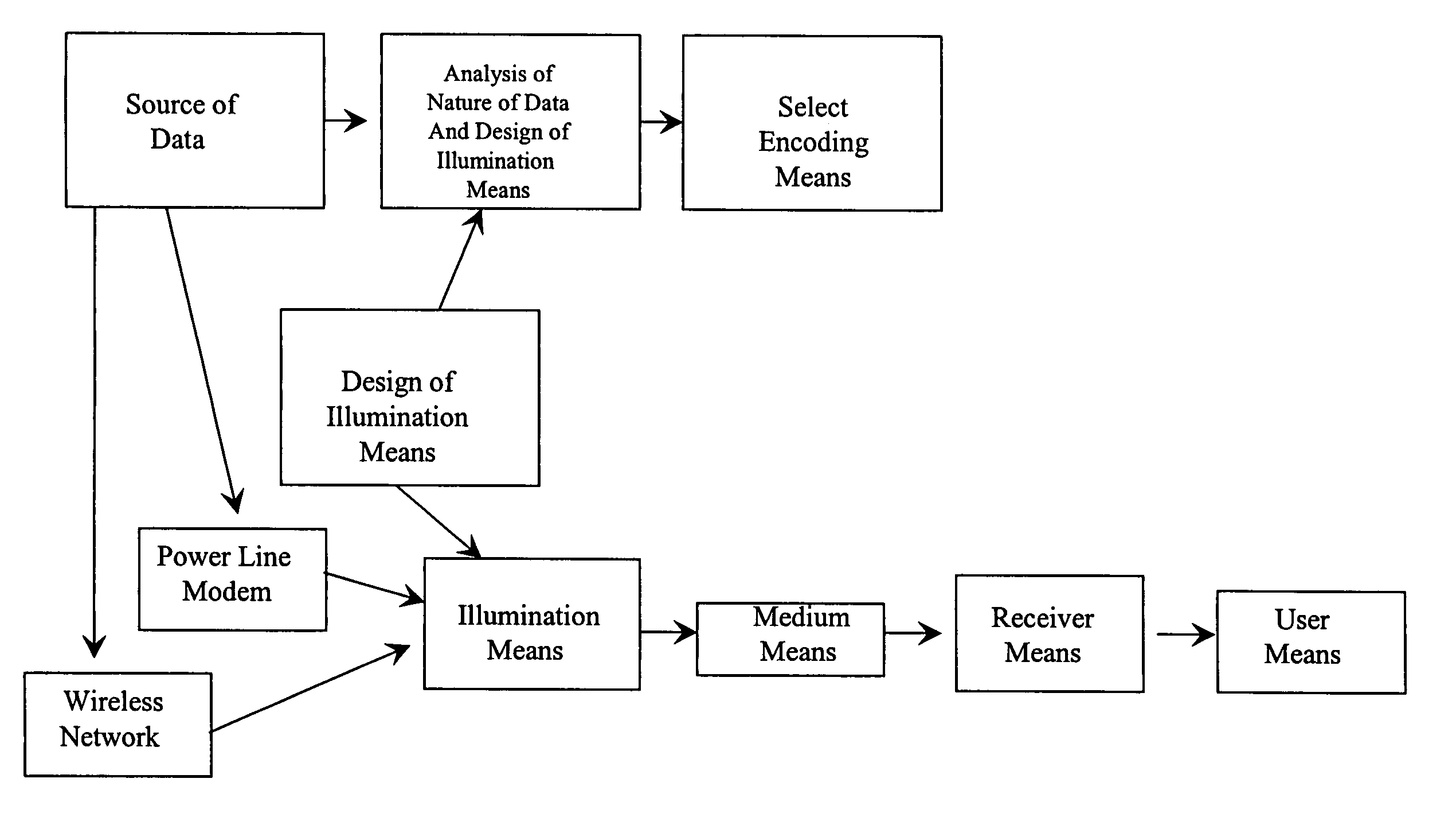
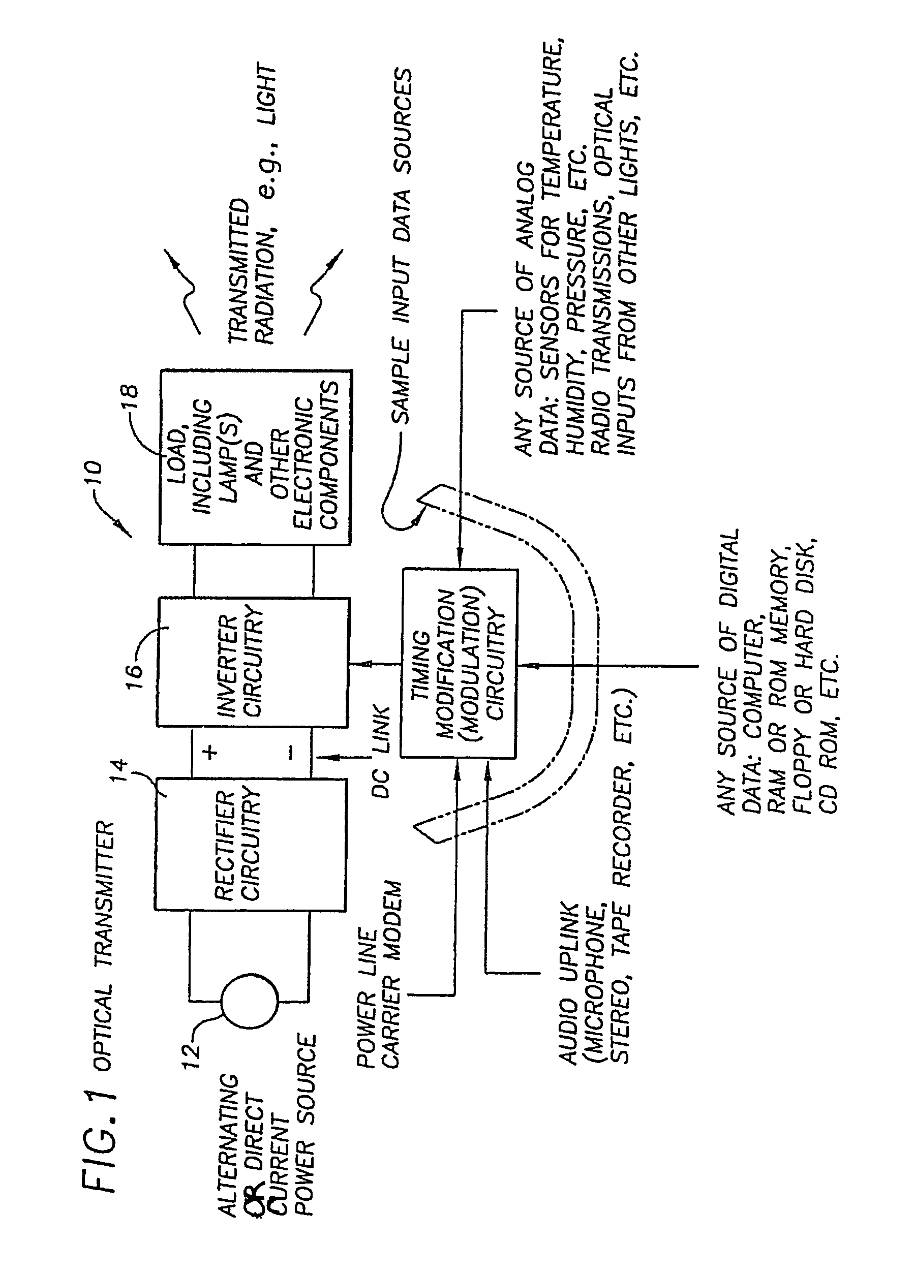
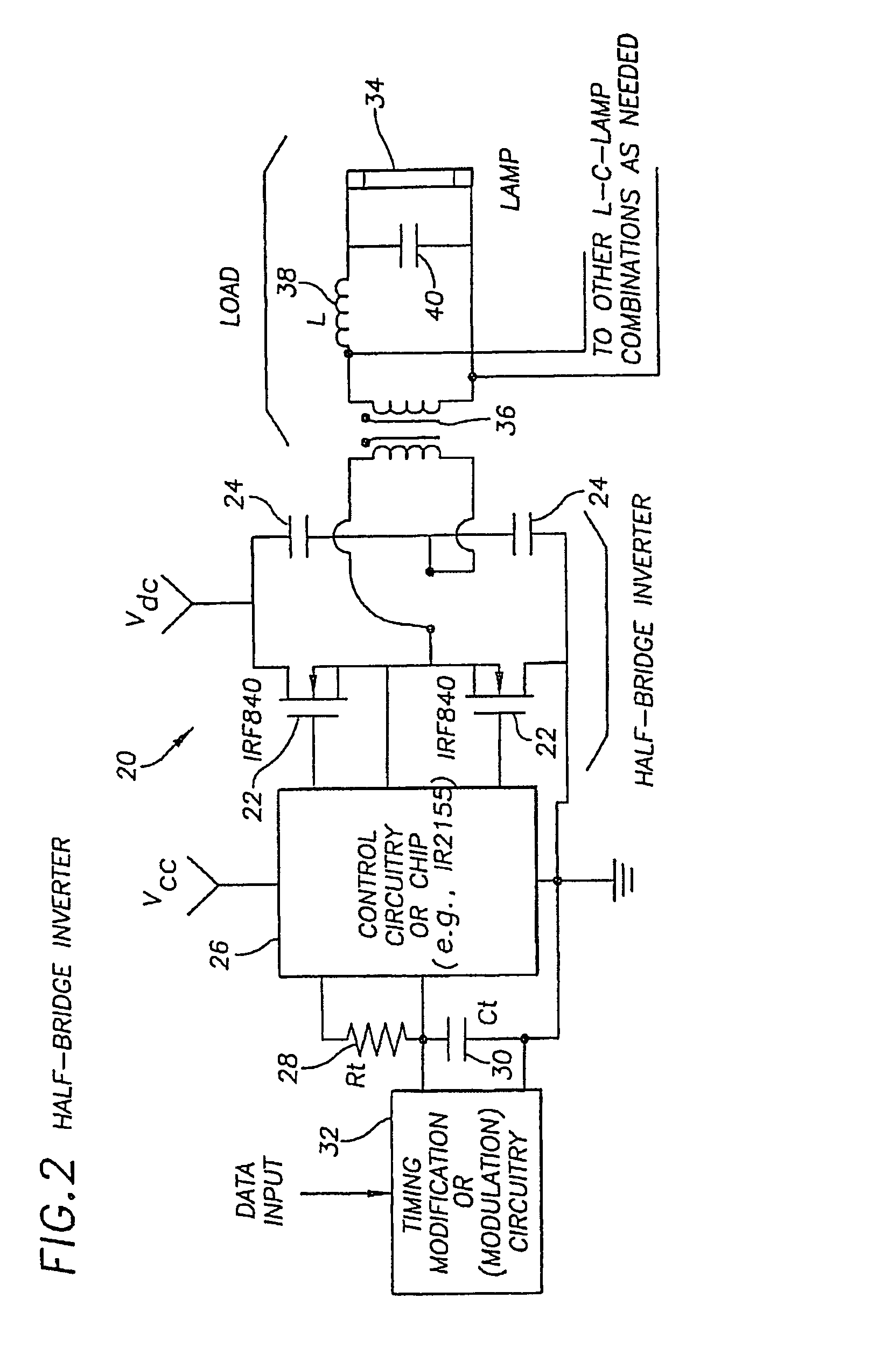
[0085]The present invention transmits information over a free space optical data pathway. Transmission is accomplished by modulating or varying the frequency of the alternating current in an electric discharge lamp such as a fluorescent lamp. A typical discharge lamp requires a relatively high starting or striking voltage across it's terminals to form an arc or electric discharge in the lamp. Once the arc forms, it is essential to reduce the voltage across the lamp, lest an excessive current flow through the lit lamp, destroying it. The purpose of an electronic lamp ballast is at least two-fold, therefore. The ballast must provide an adequately high voltage to initiate arc formation and light production. After starting, the ballast serves to limit the current through the lamp, ensuring satisfactory light production and long lamp life. The present invention adds a third function to the ballast. A means is provided to vary the frequency of the lamp current to encode information for tr...


PUM


Abstract

A system for and method of generating electromagnetic radiation in which the radiation has both a first and second utility. The electromagnetic radiation is modulated to produce electronically detectable variations to achieve the second utility, the variations not affecting the first utility. In one embodiment, the electromagnetic radiation is visible light. In this embodiment, the first utility is illumination and the second utility is the transmission of data. In another embodiment, the invention provides a lamp for generating visible light capable of providing illumination and transmitting data to a receiver. Any variations in the visible light resulting from the data transmission are imperceptible by a human eye regardless of the nature of the data being transmitted. In yet another embodiment, a power line carrier modem or wireless network may be used with the present invention to transmit information to the source.

Description

CROSS-REFERENCE TO RELATED APPLICATIONS[0001]This application is a continuation-in-part of and claims priority to U.S. patent application Ser. No. 10 / 201,378 filed on Jul. 23, 2002 now U.S. Pat. No. 6,794,831, which claims priority to U.S. Provisional Patent Application 60 / 308,486 filed Jul. 25, 2001, U.S. Provisional Patent Application 60 / 311,037 filed Aug. 9, 2001, U.S. Provisional Patent Application 60 / 326,277 filed Oct. 1, 2001, U.S. Provisional Patent Application 60 / 338,912 filed Nov. 26, 2001, U.S. Provisional Patent Application 60 / 337,491 filed Nov. 26, 2001, U.S. Provisional Patent Application 60 / 341,191 filed Dec. 7, 2001, U.S. Provisional Patent Application 60 / 353,253 filed Feb. 1, 2002 and U.S. Provisional Patent Application 60 / 367,393 filed Mar. 25, 2002. Application Ser. No. 10 / 201,378 is a continuation-in-part of and claims priority to application Ser. No. 09 / 770,806 filed Jan. 26, 2001 now U.S. Pat. No. 6,426,599 issued Jul. 30, 2002 which claims priority to and incor...

Claims


Application Information

Patent Timeline
IPC IPC(8): G02B5/28G08B25/00
CPCH04B10/116H04B10/1149
Inventor LEEB, STEVEN B.LIVSHIN, GARYAVESTRUZ, AL-THADDEUSHINMAN, RODERICK T.LUPTON, ELMER C.JACKSON, DERON K.HOVORKA, GEORGE B.
Owner SIGNIFY HLDG BV
Why Eureka
Try Eureka