Mixer circuit arrangement and an image-reject mixer circuit arrangement

a mixer circuit and mixer circuit technology, applied in the field of mixer circuit arrangement and image rejection mixer circuit arrangement, can solve the problems of low current consumption of mixer circuit b>20/b>, low efficiency of mixer circuit, and high flicker noise, so as to facilitate demodulation and processing of received signals, improve the performance characteristics of the subject mixer circuit arrangement, and improve the effect of linearity

Inactive Publication Date: 2006-03-21
INTEL CORP
View PDF10 Cites 43 Cited by
  • Summary
  • Abstract
  • Description
  • Claims
  • Application Information

AI Technical Summary

Benefits of technology

[0013]An image-reject circuit in accordance with the present invention offers many advantages. A particular advantage in accordance with aspects of the present technology corresponds to the beneficial use of the disclosed mixer circuit in RF communications devices, especially those transmitting and receiving relatively high frequency signals. Such a mixer circuit can be used in a radio communications receiver to facilitate demodulation and processing of a received signal. Exemplary devices that may utilize such a radio communications device include cellular phones, computers, satellite communication receivers, and other devices in a wired or wireless network environment.
[0014]A still further advantage of the present technology corresponds to improved performance characteristics of the subject mixer circuit arrangements as compared with the disclosed prior art configurations. Selected exemplary embodiments of the disclosed technology are characterized by good linearity characteristics and a conversion gain of at least about 6.5 dB. Some embodiments of the technology disclosed herein are capable of providing for a conversion gain from input to output of about 11.0 dB. This gain may be even higher in a circuit with different input variables and signal characteristics.

Problems solved by technology

Mixer circuits for high frequency applications constructed using metal oxide semiconductor (MOS) transistors are subject to a limited voltage supply (usually less than 2 volts) and high levels of flicker noise, having frequencies extending up to several tens of MHz.
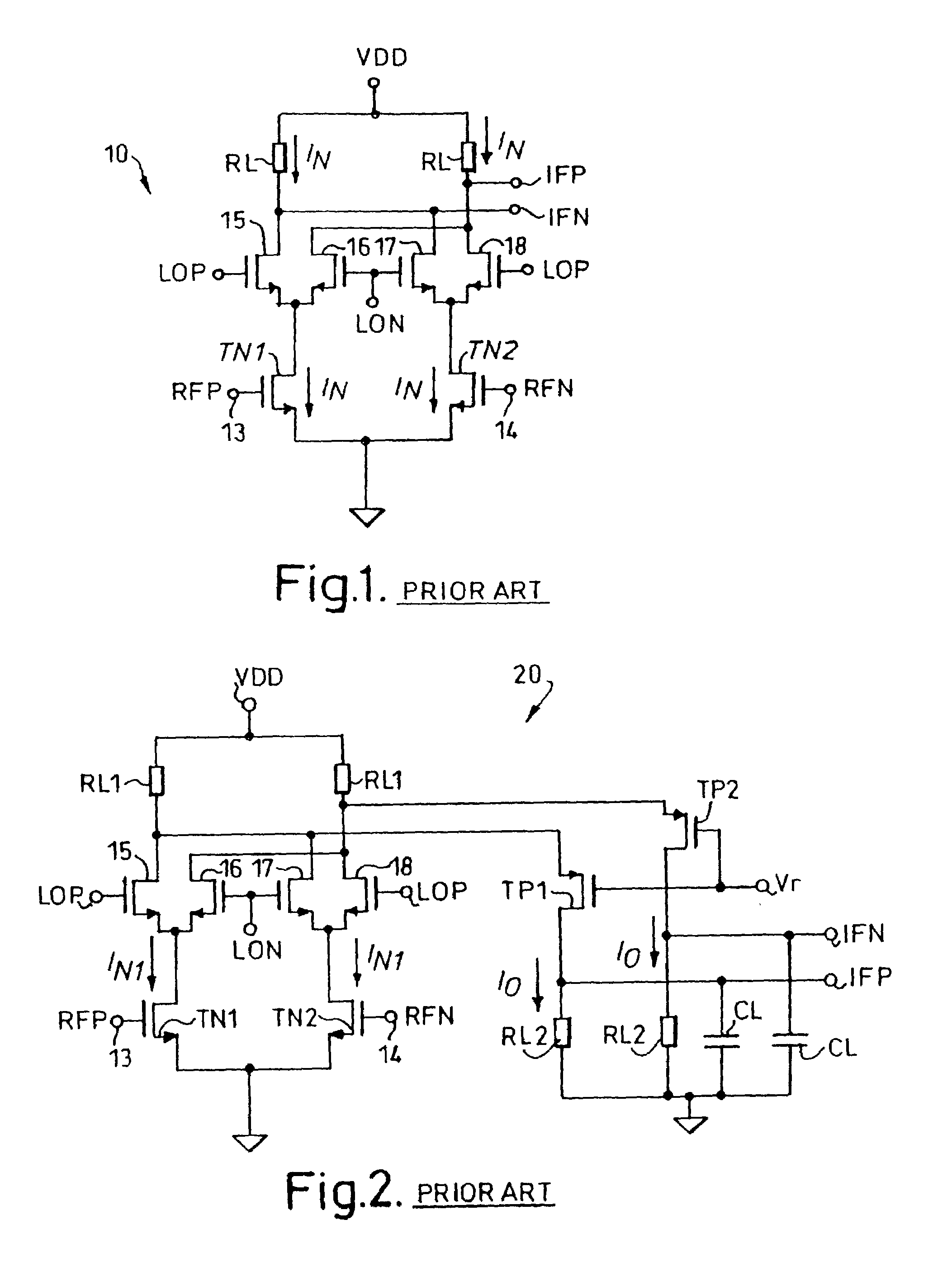
The arrangement described in the Karanicolas paper mentioned above has not proved to be practical since it requires approximately double the amount of headroom of the equivalent conventional circuit.
However, the mixer circuit 20 has relatively high current consumption because the transistors TN1 and TN2 must be biased with high dc currents in order to provide a linear current response.

Method used


Image

  • Mixer circuit arrangement and an image-reject mixer circuit arrangement
  • Mixer circuit arrangement and an image-reject mixer circuit arrangement
  • Mixer circuit arrangement and an image-reject mixer circuit arrangement

Examples


Embodiment Construction

[0023]Reference now will be made in detail to the presently preferred embodiments of the invention, one or more examples of which are illustrated in the accompanying drawings. Each example is provided by way of explanation of the invention, which is not restricted to the specifics of the examples. In fact, it will be apparent to those skilled in the art that various modifications and variations can be made in the present invention without departing from the scope or spirit of the invention. For instance, features illustrated or described as part of one embodiment, can be used on another embodiment to yield a still further embodiment. Thus, it is intended that the present invention cover such modifications and variations as come within the scope of the appended claims and their equivalents. The same numerals are assigned to the same components throughout the drawings and description.

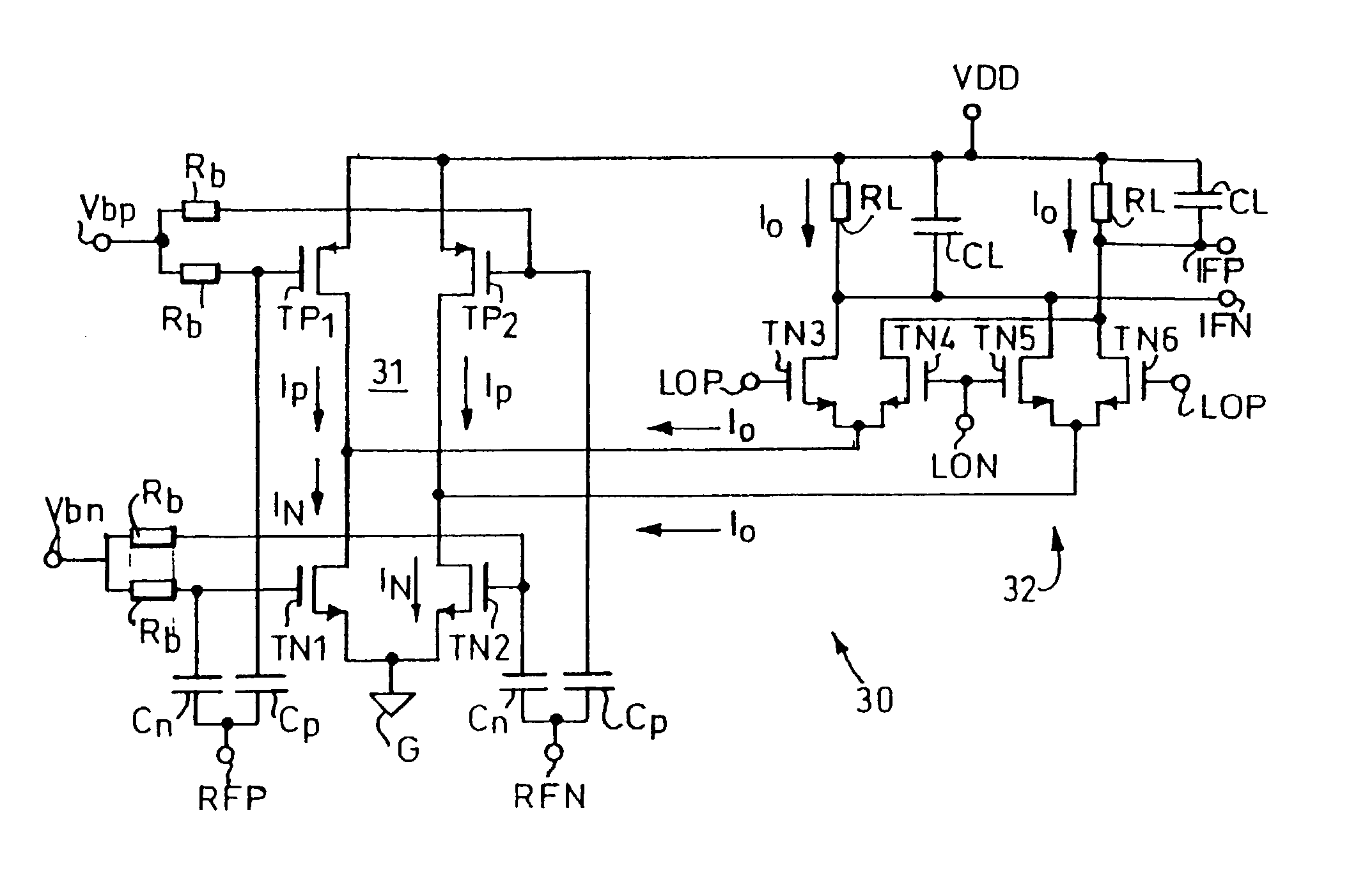
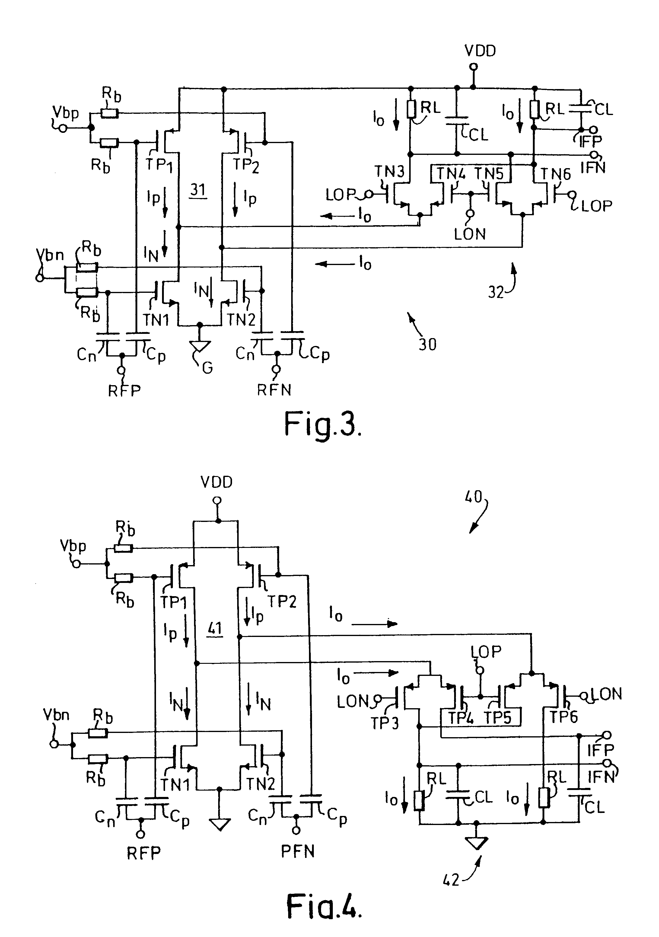
[0024]Referring to FIG. 3, a mixer circuit arrangement 30 in accordance with the invention comprises g...


PUM


Abstract

A mixer circuit arrangement 30 comprises a complementary transconductor circuit 31 and a mixer stage 32. The complementary transconductor circuit 31 includes two paths in parallel between a positive supply voltage VDD and ground G and is connected directly between the voltage supply terminals VDD and G. The first path includes a P-type MOS transistor TP1 and an N-type MOS transistor TN1 connected in series. Similarly, the second path includes a P-type MOS transistor TP2 and an N-type MOS transistor TN2 connected in series. The gate electrodes of the P-type transistors TP1 and TP2 are connected to a voltage bias Vbp via high value bias resistors Rb, and the gate electrodes of the N-type transistors TN1 and TN2 are connected to a second voltage bias Vbn via high value bias resistors Rb. The mixer stage 32 is connected between the output of the complementary transconductor circuit 31 and a load, the load also being connected to one of the supply terminals.

Description

CROSS-REFERENCE TO RELATED APPLICATIONS[0001]The present application claims priority to currently pending United Kingdom Patent Application number 0116475.5, filed on Jul. 5, 2001.STATEMENT REGARDING FEDERALLY SPONSORED RESEARCH OR DEVELOPMENT[0002]N / ABACKGROUND OF THE INVENTION[0003]The present invention relates to a mixer circuit arrangement and to an image-reject mixer circuit arrangement.[0004]Mixer circuits for high frequency applications constructed using metal oxide semiconductor (MOS) transistors are subject to a limited voltage supply (usually less than 2 volts) and high levels of flicker noise, having frequencies extending up to several tens of MHz. Accordingly, the gain and output signal level required in such mixer circuits are greater than those required in the equivalent bipolar circuits.[0005]It is known to construct a mixer circuit using MOS transistors using an arrangement translated directly from the conventional bipolar Gilbert cell mixer. Such MOS mixer circuits ...

Claims


Application Information

Patent Timeline
Patent Type & Authority Patents(United States)
IPC IPC(8): H04B1/26H03D7/14
CPCH03D7/1441H03D7/1458H03D7/1483H03D7/1491H03D2200/0084H03D2200/0033H03D2200/0043
Inventor SOUETINOV, VIATCHESLAV IGOREVICH
Owner INTEL CORP
Why Eureka
Try Eureka