Methods of forming aluminum-comprising physical vapor deposition targets; sputtered films; and target constructions

a technology of physical vapor deposition and target, which is applied in the direction of vacuum evaporation coating, coating, sputtering coating, etc., can solve the problems of limiting the practicability of tmp processes, affecting the development of tooling and processing, and usually not wanting structural components

Inactive Publication Date: 2006-03-28
HONEYWELL INT INC
View PDF34 Cites 27 Cited by
  • Summary
  • Abstract
  • Description
  • Claims
  • Application Information

AI Technical Summary

Benefits of technology

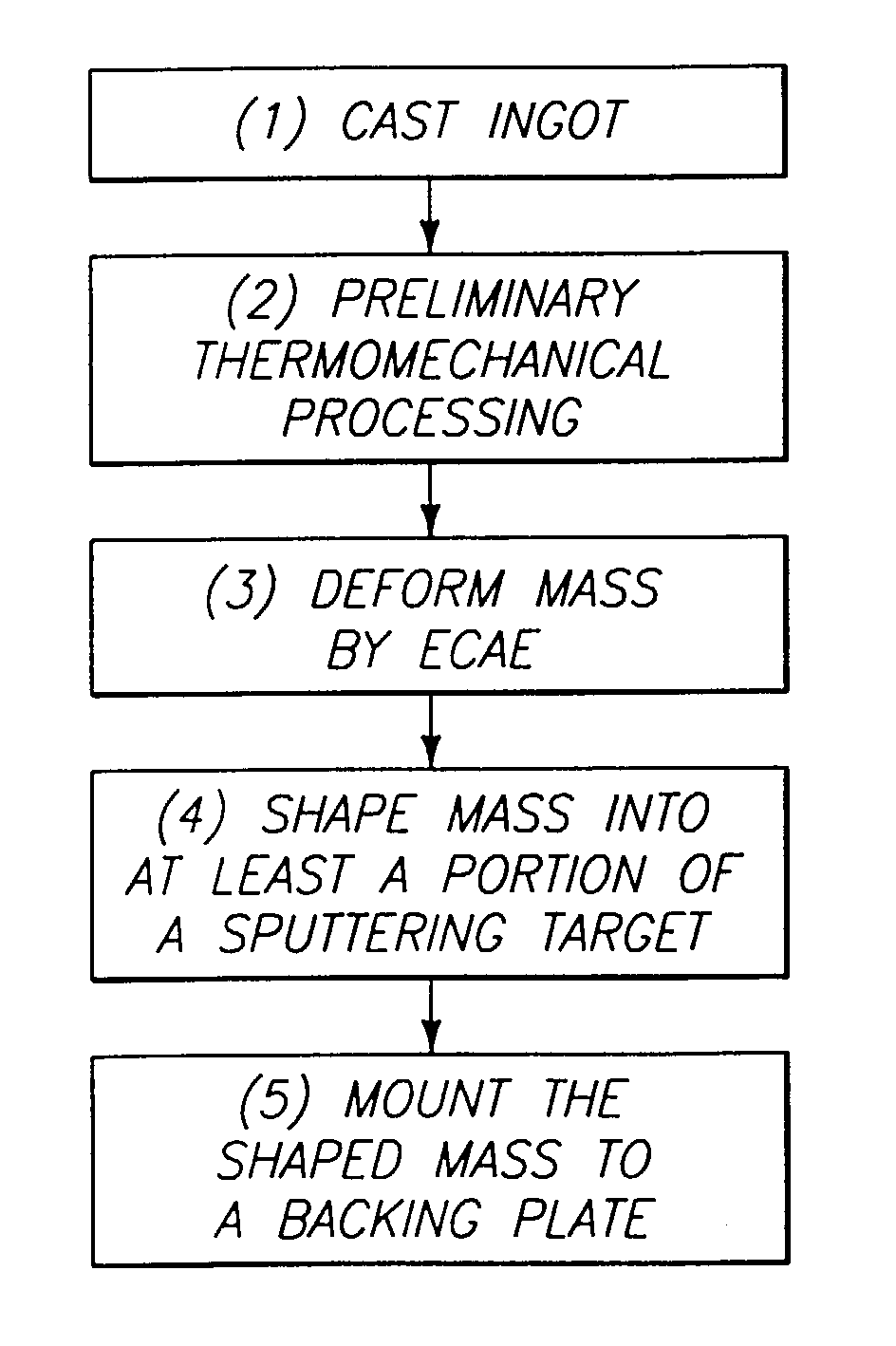
[0016]In one aspect, the invention includes a method of forming an aluminum-comprising physical vapor deposition target. An aluminum-comprising mass is deformed by equal channel angular extrusion, with the mass being at least 99.99% aluminum and further comprising less than or equal to about 1,000 ppm of one or more dopant materials comprising elements selected from the group consisting of Ac, Ag, As, B, Ba, Be, Bi, C, Ca, Cd, Ce, Co, Cr, Cu, Dy, Er, Eu, Fe, Ga, Gd, Ge, Hf, Ho, In, Ir, La, Lu, Mg, Mn, Mo, N, Nb, Nd, Ni, O, Os, P, Pb, Pd, Pm, Po, Pr, Pt, Pu, Ra, Rf, Rh, Ru, S, Sb, Sc, Se, Si, Sm, Sn, Sr, Ta, Tb, Te, Ti, Tl, Tm, V, W, Y, Yb, Zn and Zr. After the aluminum-comprising mass is deformed, the mass is shaped into at least a portion of a sputtering target. The sputtering target can ultimately be formed to be either a monolithic or mosaic sputtering target.
[0017]In another aspect, the invention encompasses a method of forming an aluminum-comprising physical vapor deposit

Problems solved by technology

Such massive dimensions present challenges to the development of tooling and processing for fabrication of suitable aluminum-comprising targets.
These structural components are usually not desired and can be sources for arcing as well as contamination of thin films.
Because forging and rolling operations change the shape of billets by reducing their thickness, practically attainable strains in today's TMP processes are restricted.
Further, rolling and forging operations generally produce non-uniform straining throughout a billet.
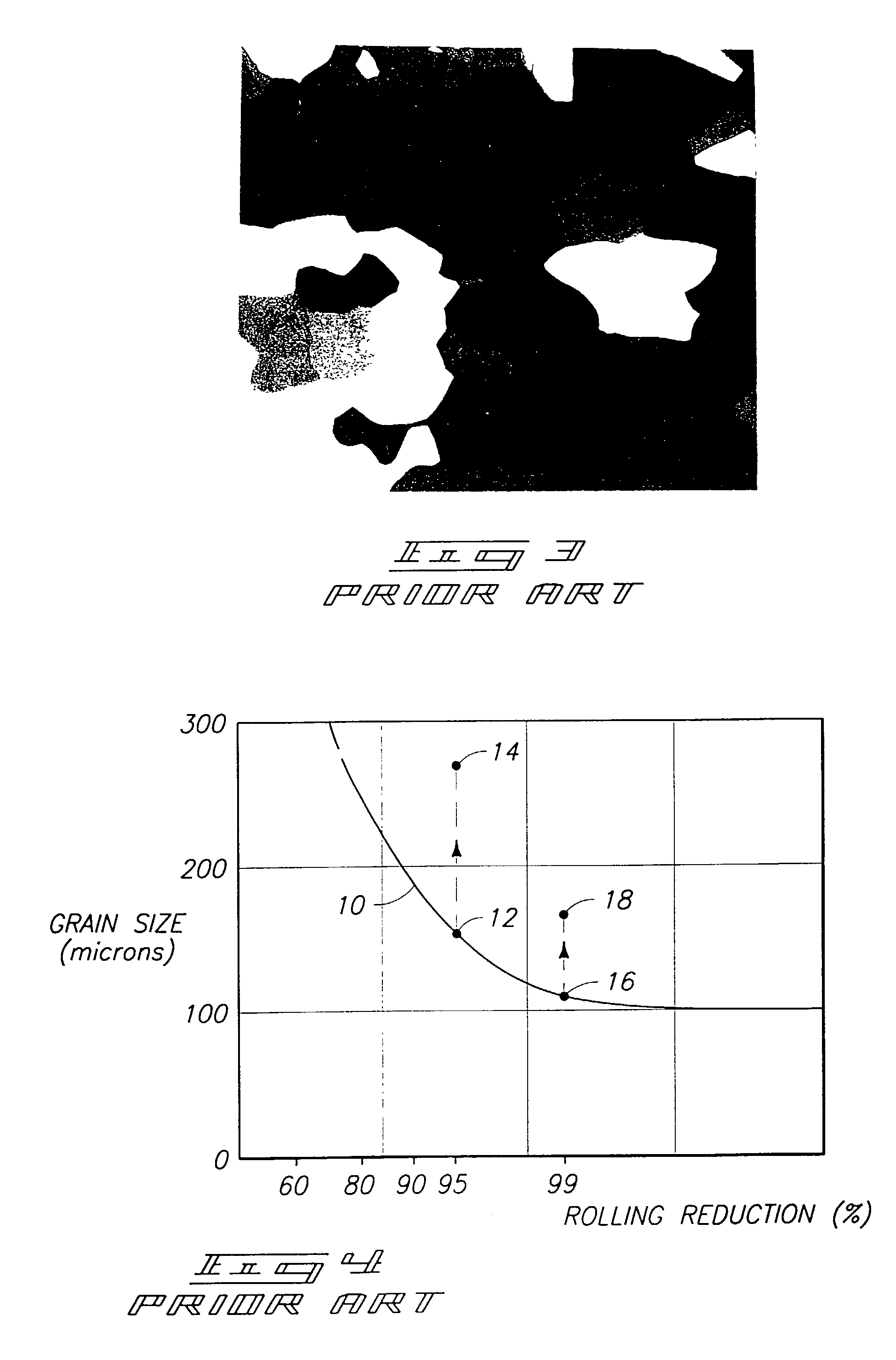
The conventional reductions of 85% to 92% can provide static recrystallization of high purity aluminum (for instance, aluminum having a purity of 99.9995% or greater) but they are not sufficient to develop the fine and uniform grain structure desired for flat panel display target materials.
Further, the structures achieved by conventional processes are not stable.
A difficulty that occurs when the doping elements are incorporated is that full s

Method used


Image

  • Methods of forming aluminum-comprising physical vapor deposition targets; sputtered films; and target constructions
  • Methods of forming aluminum-comprising physical vapor deposition targets; sputtered films; and target constructions
  • Methods of forming aluminum-comprising physical vapor deposition targets; sputtered films; and target constructions

Examples


example 1

High-Purity Aluminum Having 30 ppm Si Therein, and Processed in Accordance with Methodology of the Present Invention

[0077]As-cast material defined as 5N5 Al and 30 ppm Si is processed via hot forging at 75% reduction and ECAE for 6 passes via route D. The material has a fully recrystallized structure with grain size of 15 μm. Subsequent rolling with a reduction of 85% grew the average grain size to 20 μm with an aspect ratio of about 1.5. Annealing at a temperature of 150° C. for 1 hour, which was estimated as the highest temperature expected during a subsequent sputtering process, resulted in an insignificant grain growth to 23 μm. During a long (16 hours) exposure to 150° C., grains grew to 28 μm. Also, a temperature increase to 200° C. for 1 hour yielded a similar grain size of about 30 μm. Therefore, ECAE plus rolling provides a fine and uniform structure for a material of 5N5 Al and 30 ppm Si, with an average grain size of less than or equal to about 30 μm which is stable for s...

example 2

High-Purity Aluminum Having 10 ppm Silicon Therein, and Processed Accordance with Methodology of the Present Invention

[0078]Samples were cast, hot forged at 74% reduction and ECAE extruded for 6 passes via route D. A Structure after ECAE is fully dynamically recrystallized with an average grain size of about 19 μm. Subsequent rolling at 85%, and annealing at 150° C. for 1 hour yields a fully recrystallized grain size of around 35 μm.

example 3

High-Purity Aluminum Having 10 ppm Sc Therein, and Processed in Accordance with Methodology of the Present Invention

[0079]Samples were cast, hot forged at 74% reduction, and ECAE extruded for 6 passes via route D. A structure after ECAE is fully dynamically recrystallized with an average grain size of about 26 μm. During rolling up to a reduction of 60%, the structure remains stable and typical for heavily-rolled materials. After 70% reduction, first recrystallized grains are observed. At 85% rolling reduction, about 60% of the sample area was fully recrystallized with an average grain size of about 45 μm.


PUM

PropertyMeasurementUnit
Grain sizeaaaaaaaaaa
Temperatureaaaaaaaaaa
Fractionaaaaaaaaaa

Abstract

The invention includes a method of forming an aluminum-comprising physical vapor deposition target. An aluminum-comprising mass is deformed by equal channel angular extrusion. The mass is at least 99.99% aluminum and further comprises less than or equal to about 1,000 ppm of one or more dopant materials comprising elements selected from the group consisting of Ac, Ag, As, B, Ba, Be, Bi, C, Ca, Cd, Ce, Co, Cr, Cu, Dy, Er, Eu, Fe, Ga, Gd, Ge, Hf, Ho, In, Ir, La, Lu, Mg, Mn, Mo, N, Nb, Nd, Ni, O, Os, P, Pb, Pd, Pm, Po, Pr, Pt, Pu, Ra, Rf, Rh, Ru, S, Sb, Sc, Se, Si, Sm, Sn, Sr, Ta, Tb, Te, Ti, Tl, Tm, V, W, Y, Yb, Zn and Zr. After the aluminum-comprising mass is deformed, the mass is shaped into at least a portion of a sputtering target. The invention also encompasses a physical vapor deposition target consisting essentially of aluminum and less than or equal to 1,000 ppm of one or more dopant materials comprising elements selected from the group consisting of Ac, Ag, As, B, Ba, Be, Bi, C, Ca, Cd, Ce, Co, Cr, Cu, Dy, Er, Eu, Fe, Ga, Gd, Ge, Hf, Ho, In, Ir, La, Lu, Mg, Mn, Mo, N, Nb, Nd, Ni, O, Os, P, Pb, Pd, Pm, Po, Pr, Pt, Pu, Ra, Rf, Rh, Ru, S, Sb, Sc, Se, Si, Sm, Sn, Sr, Ta, Tb, Te, Ti, Tl, Tm, V, W, Y, Yb, Zn and Zr. Additionally, the invention encompasses thin films.

Description

CROSS REFERENCE TO RELATED APPLICATION[0001]This application is a divisional of U.S. patent application Ser. No. 09 / 783,377 which was filed on Feb. 13, 2001, which claims priority to U.S. Provisional Application Ser. No. 60 / 193,354 which was filed on Mar. 28, 2000, both of which are incorporated by reference herein.TECHNICAL FIELD[0002]The invention pertains to methods of forming aluminum-comprising physical vapor deposition targets, and to target constructions. In particular applications, the invention pertains to methods of utilizing equal channel angular extrusion (ECAE) to deform an aluminum-comprising mass in forming a physical vapor deposition (PVD) target for use in the manufacture of flat panel displays (FPDs), such as, for example, liquid crystal displays (LCDs).BACKGROUND OF THE INVENTION[0003]PVD is a technology by which thin metallic and / or ceramic layers can be sputter-deposited onto a substrate. Sputtered materials come from a target, which serves generally as a cathod...

Claims


Application Information

Patent Timeline
IPC IPC(8): B21C23/00C22C21/00C22F1/00C22F1/04C23C14/34
CPCC22F1/04C23C14/3414Y10S72/70C23C14/14
Inventor SEGAL, VLADIMIR M.LI, JIANXINGALFORD, FRANKFERRASSE, STEPHANE
Owner HONEYWELL INT INC
Why Eureka
Try Eureka