Pressure container

a pressure container and container body technology, applied in the field of containers, can solve the problems of inability to produce via injection molding a unitary, bottle failure, inability to meet the requirements of production, etc., and achieve the effect of inexpensive production

Active Publication Date: 2006-03-28
SC JOHNSON & SON INC
View PDF13 Cites 11 Cited by
  • Summary
  • Abstract
  • Description
  • Claims
  • Application Information

AI Technical Summary

Benefits of technology

[0039]Thus, the invention achieves the goat of a pressure resistant container that can be inexpensively produced fro

Problems solved by technology

However, the blow-molding process is inherently less precise in controlling wall thickness and features than are other techniques for molding plastics.
This presents an increasing problem when it is desired to contain materials at increasing pressures.
At some point, flaws or other weaker bottle locations will give way, causing bottle failure even though most of the bottle is still strong enough to contain the pressure.
However, it is very difficult, and in many instances entirely impractical, to produce via injection molding a unitarily formed bottle with a necked-in top.
There is no way to withdraw through the necked-in top the part of the mold that defines the bottle's larger internal shape.
These means of manufacture require special equipment and also leave one or more plastic-to-plastic seams that can be points of inconsistent thickness or plastic crystal structure or other structural inconsistencies that can lead to an increased likelihood of failure under sufficiently challenging pressures.
By whatever technique they are f

Method used


Image

  • Pressure container
  • Pressure container
  • Pressure container

Examples


first embodiment

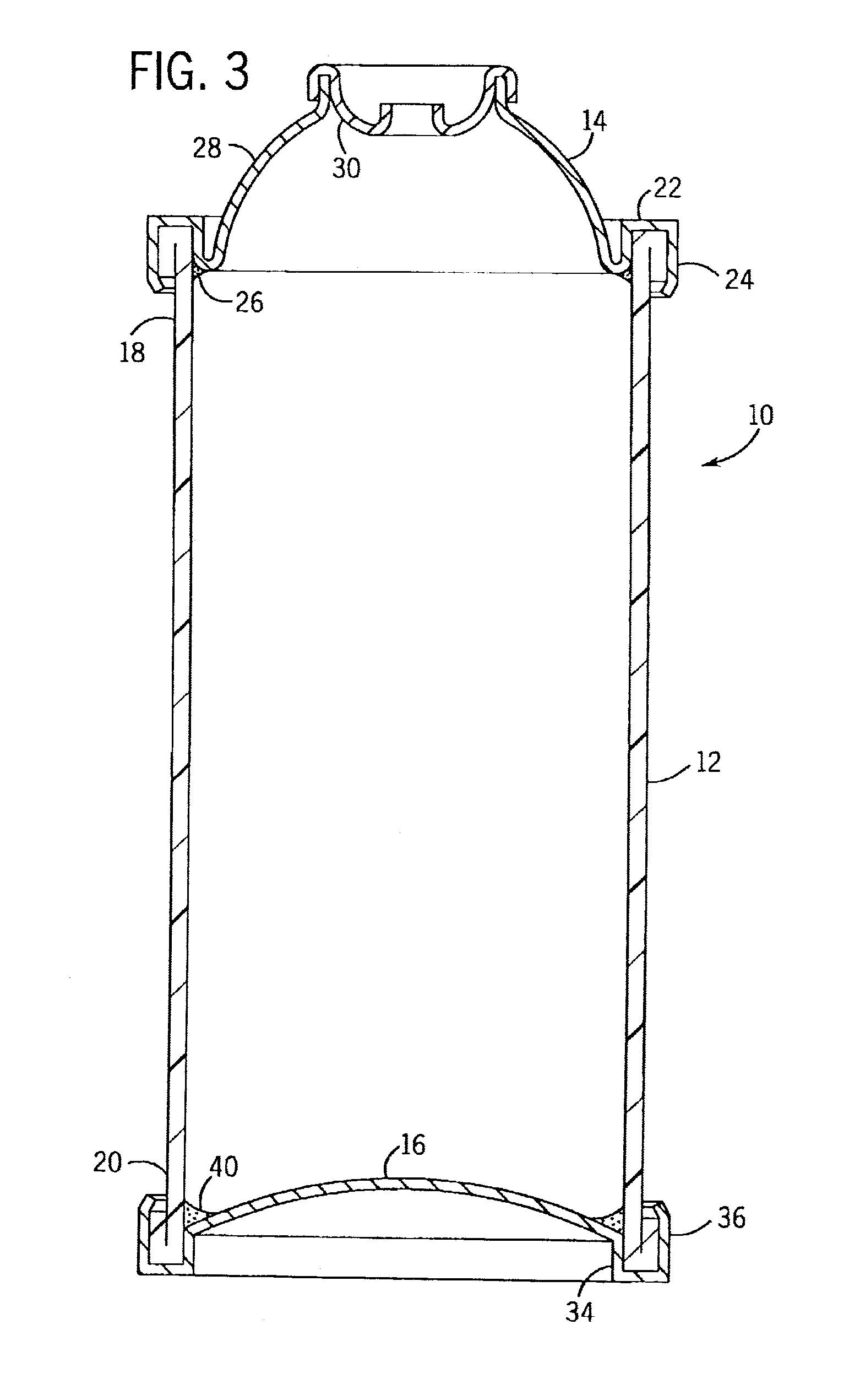
[0046]Turning now to the drawings, wherein like and corresponding reference numbers refer to analogous corresponding parts throughout the several views, in the present invention a pressure container is shown generally at 10 in FIG. 3. The pressure container 10 has side walls 12, a metal top 14, and metal bottom 16. The side walls 12 are made of a selected plastic, which may be selected to be transparent, translucent, or opaque.

[0047]Transparent side walls 12 are preferred in that they allow container contents to be displayed to a user, and also show a user something about the condition, color, amount, and the like regarding the contents. Preferably, the side walls 12 are made of a plastic selected from the group consisting of PET, PEN, polycarbonate, polyacrylamide, and mixtures thereof.

[0048]The side walls 12 extend axially and have a top end 18 and a bottom end 20. The metal top 14 is attached to the top end 18 of the side walls 12 in pressure-containing relation at a top seam 22....

embodiment 110

[0053]In a more preferred form, structures are provided in the FIG. 4 embodiment 110 which help reduce the need for such sealants and gaskets still further. Features of the FIG. 4 embodiment that are analogous to the FIG. 3 embodiment features are given similar numbers, albeit indexed by 100. We are not discussing some of these separately in the context of FIG. 4. However, a cross reference to the discussion of FIG. 3 will assist in understanding the structure further.

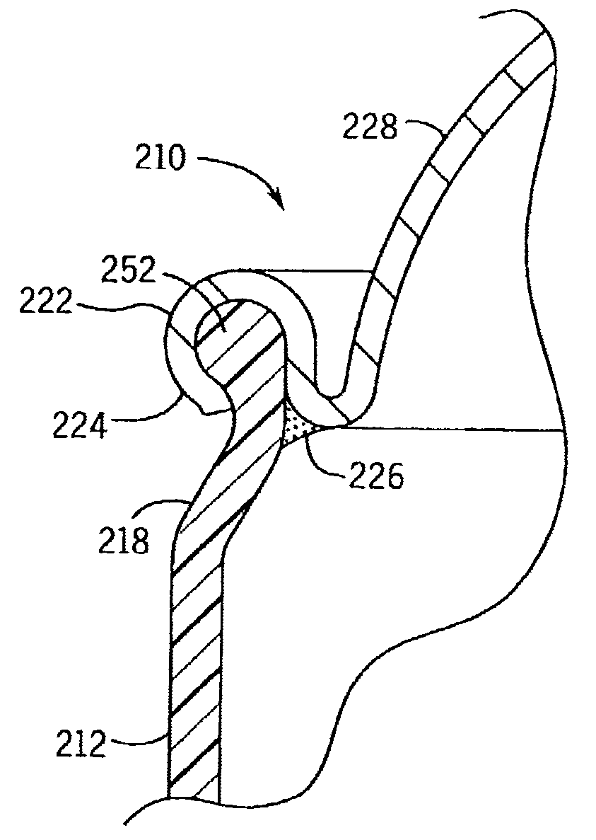
[0054]In any event, the side walls 112 of the FIG. 4 pressure container 110 differ from the corresponding structure of the pressure container shown at 10 in FIG. 3 in that they include at least one of a bottom bead 150 at the side walls' bottom end 120 and at least one top bead 152 at the side walls' top end 118. Alternatively, there could either be just one top bead but no bottom bead, or just one bottom bead but no top bead. However, having both beads is highly preferred.

[0055]Side walls 112 have such features that a...


PUM

PropertyMeasurementUnit
Fractionaaaaaaaaaa
Fractionaaaaaaaaaa
Fractionaaaaaaaaaa

Abstract

A pressure container comprising axially extending side walls formed of plastic extending between a top end and a bottom end. A metal top is attached at a top seam in pressure-containing relation to the top end of the side walls, and a metal bottom attached at a bottom seam in pressure-containing relation to the bottom end of the side walls. Optional top and bottom beads are formed in the side walls to aid in sealingly securing the metal top and bottom to the side walls. A method for containing pressurized materials by providing and filling such a pressure container is also shown.

Description

CROSS-REFERENCE TO RELATED APPLICATIONS[0001]This application claims priority based on U.S. provisional application 60 / 367,408, which was filed Mar. 25, 2002.STATEMENT REGARDING FEDERALLY SPONSORED RESEARCH / DEVELOPMENT[0002]Not applicableFIELD OF THE INVENTION[0003]The present invention relates to containers that are particularly adapted for containing pressurized materials including, but not limited to, pressurized gases either alone or in combination with liquids, gels, or other materials commonly dispensed under pressure from containers.BACKGROUND OF THE INVENTION[0004]There are a variety of known bottles and cans designed to contain pressurized materials. These include metal cans, such as those commonly used in conventional aerosol products, as well as plastic bottles, such as those commonly used for containing pressurized beverages. At least in laboratory settings, it is also known to use glass bottles to contain the sort of materials that, in the consumer market, are normally ...

Claims


Application Information

Patent Timeline
IPC IPC(8): B65D6/28B65D8/04B65D8/08B65D8/18F17C1/14F17C1/16
CPCB65D83/38F17C1/16F17C1/14F17C2270/0718F17C2201/0109F17C2201/0114F17C2201/032F17C2201/058F17C2203/066F17C2203/0663F17C2203/0697F17C2205/018F17C2205/0323F17C2209/2118F17C2209/22F17C2209/234F17C2223/0123F17C2223/035F17C2260/011
Inventor MEILAND, NICO J.FLASHINSKI, STANLEY J.
Owner SC JOHNSON & SON INC
Why Eureka
Try Eureka