Railway track circuits

a technology of track circuits and railways, applied in the field of railway track circuits, to achieve the effect of high form factor

Inactive Publication Date: 2006-03-28
SIEMENS RAIL AUTOMATION HLDG
View PDF15 Cites 20 Cited by
  • Summary
  • Abstract
  • Description
  • Claims
  • Application Information

AI Technical Summary

Benefits of technology

[0007]Preferably, the QPSK signal is constrained to a narrow frequency band to produce a QPSK signal with a...

Problems solved by technology

A fundamental difficulty with track circuits on modem electrified railways is that they must share the railway track with the traction return, and track circuits have consistently evolved to provide bette...

Method used


Image

  • Railway track circuits
  • Railway track circuits
  • Railway track circuits

Examples


Embodiment Construction

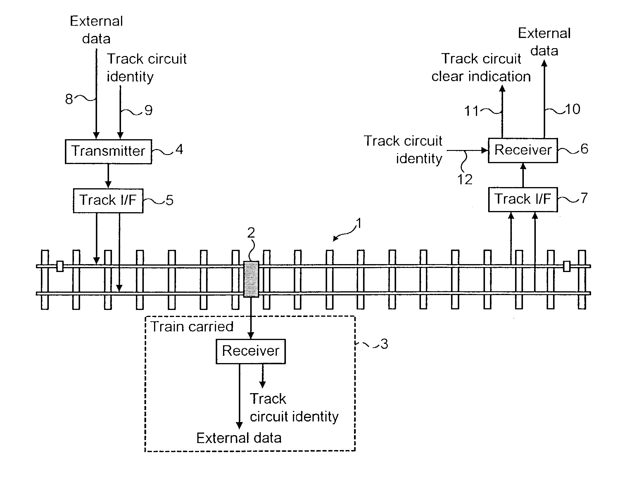
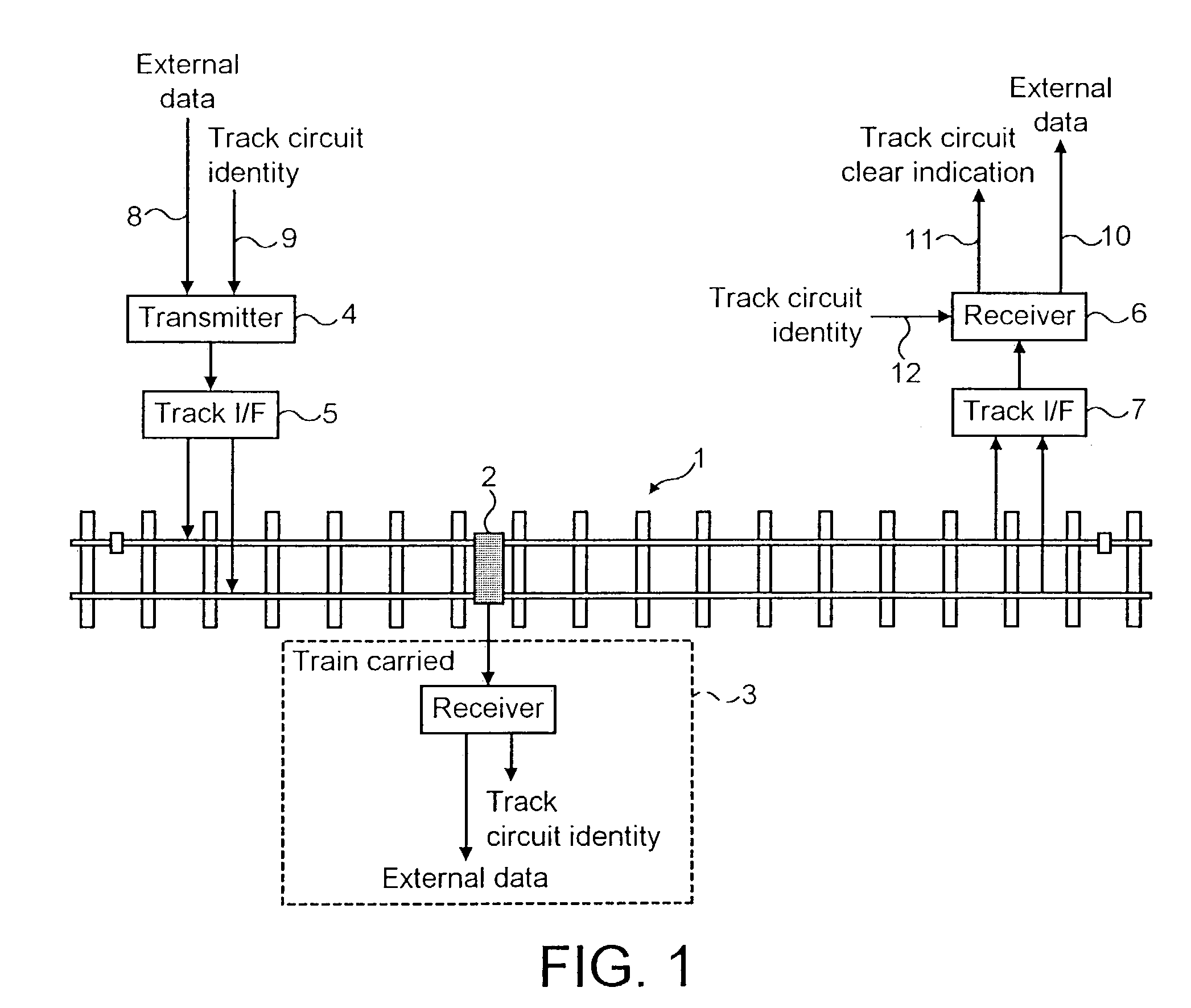
[0017]In railway track circuit apparatus, the use of a Phase Shift Keying (PSK) modulation technique offers the generation and detection of a more unique signal, offering improved discrimination between a track circuit signal and interference from other tracks or the traction return system. Further, there are applications where it is also desirable to carry information along the track circuit to reduce the need for additional trackside communications or track-to-train communications and PSK offers an improved information rate for a given bandwidth, which facilitates this while still fulfilling a train detection role.

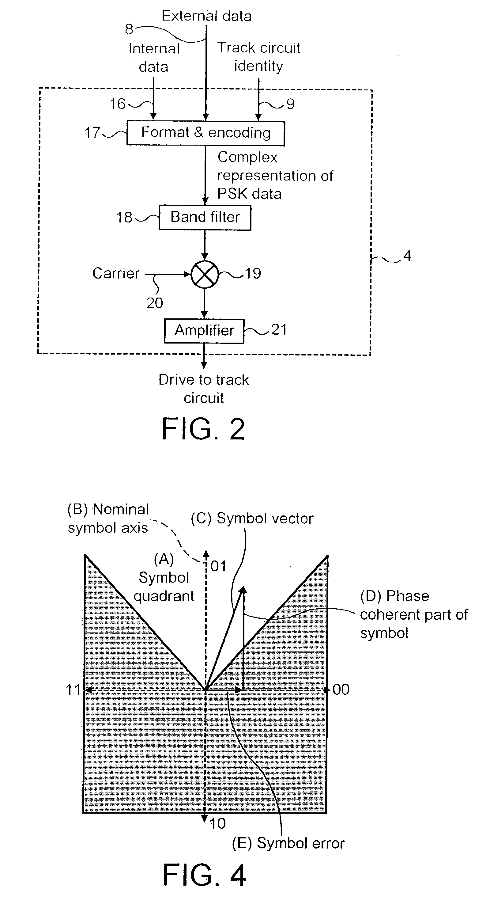
[0018]When a PSK signal is band-limited to a narrow band, the signal has a relatively high peak voltage in relation to the root mean square (RMS) voltage (high form factor) and thus for a given power driven into the track circuit, the signal provides a higher voltage for breaking down rail contamination.

[0019]Referring first to FIG. 1, reference numeral 1 designates a le...


PUM


Abstract

Railway track circuit apparatus for train detection comprises a track circuit transmitter and a receiver, wherein the transmitter generates a QPSK modulated signal that is transmitted into a track circuit and which is detected by the receiver.

Description

CROSS-REFERENCE TO RELATED APPLICATION(S)[0001]This application claims priority of United Kingdom Patent Application No. 0127927.2, filed Nov. 21, 2001.BACKGROUND OF THE INVENTION[0002]The present invention relates to railway track circuits.[0003]Track circuits are a well-established means of train detection and can also be used to provide a level of broken-rail detection. A fundamental difficulty with track circuits on modem electrified railways is that they must share the railway track with the traction return, and track circuits have consistently evolved to provide better immunity to interference from traction systems. Another key concern for track circuit signals is cross-coupling between tracks, which could result in one track erroneously accepting a signal from another track. Over recent history (the last 20 years) various track circuits have evolved that use Frequency Shift Keying (FSK) to form a distinct electrical signal that is transmitted along the track. EP-A-0 165 048 d...

Claims


Application Information

Patent Timeline
IPC IPC(8): B61L21/00B61L1/18
CPCB61L1/188
Inventor MCALLISTER, LAWRENCE LAWSON
Owner SIEMENS RAIL AUTOMATION HLDG
Why Eureka
Try Eureka