Method and apparatus for providing uniform gas delivery to substrates in CVD and PECVD processes

a technology of uniform gas delivery and substrate, applied in the field of plasma enhanced chemical vapor deposition, methods and apparatus for controlling the uniformity of flux for gas delivery, can solve the problems of large hole size, inability to meet the requirements of gas flow, etc., to achieve the effect of enhancing gas diffusion and mixing

Inactive Publication Date: 2006-03-28
EUGENUS INC
View PDF3 Cites 62 Cited by
  • Summary
  • Abstract
  • Description
  • Claims
  • Application Information

AI Technical Summary

Benefits of technology

[0014]To enhance gas diffusion and mixing in embodiments of the invention the supply ports into the first channels and the transition passages from the first channels into second channels are offset in position such that no supply port is aligned with a transition passage. In preferred embodiments there are also coolant passages in the second channel region facing the inside of a reactor chamber, for protecting the showerhead apparatus from heat from within the chamber, and for impeding process film deposition on the showerhead face.

Problems solved by technology

These requirements become more critical as substrate size increases, and as device size decreases (i.e. line width) creating a need for more complexity in chamber design and gas flow techniques to maintain adequate uniformity.
Often such apparatus is adapted only for one type of process and cannot be used with other processes using the same CVD equipment.
Uneven gas flow often results if some holes are inadvertently made too large in comparison with a mean size, or placed in wrong positions.
Improvements made to manifold and diffuser designs depend largely on empirical methods in the field resulting in numerous cases of product expenditure through batch testing.
Uniform gas delivery remains a formidable challenge in the CVD processing of substrates.
If gas delivery uniformity cannot be strictly controlled, layer thickness will not be uniform.
The problem progresses with increased target size and as more layers are added.
One problem with many diffusing showerhead systems relates to limited gas flow dynamics and control capability.
Prior art diffusing methods and apparatus do not meet requirements for this type of flexibility.
Another problem in this technology is that various gases of different characteristics are mixed for a particular process.
There are variations in density, temperature, reactivity and the like, such that perfect uniformity in gas mixture composition and density at delivery still does not produce precise uniformity in layer deposition.

Method used


Image

  • Method and apparatus for providing uniform gas delivery to substrates in CVD and PECVD processes
  • Method and apparatus for providing uniform gas delivery to substrates in CVD and PECVD processes
  • Method and apparatus for providing uniform gas delivery to substrates in CVD and PECVD processes

Examples


Embodiment Construction

[0024]As described in the background section, obtaining consistent and uniform material layering in semiconductor manufacturing is paramount to producing high quality semiconductor devices. However, there are many limitations inherent to prior-art diffusing apparatus that continue to plague manufacturers using CVD or CVD-variant applications. The inventor provides in this disclosure a unique apparatus and method for enhancing process uniformity by utilizing multi-zone capabilities and strictly controlled gas delivery methods. The method and apparatus of the present invention is described in enabling detail below.

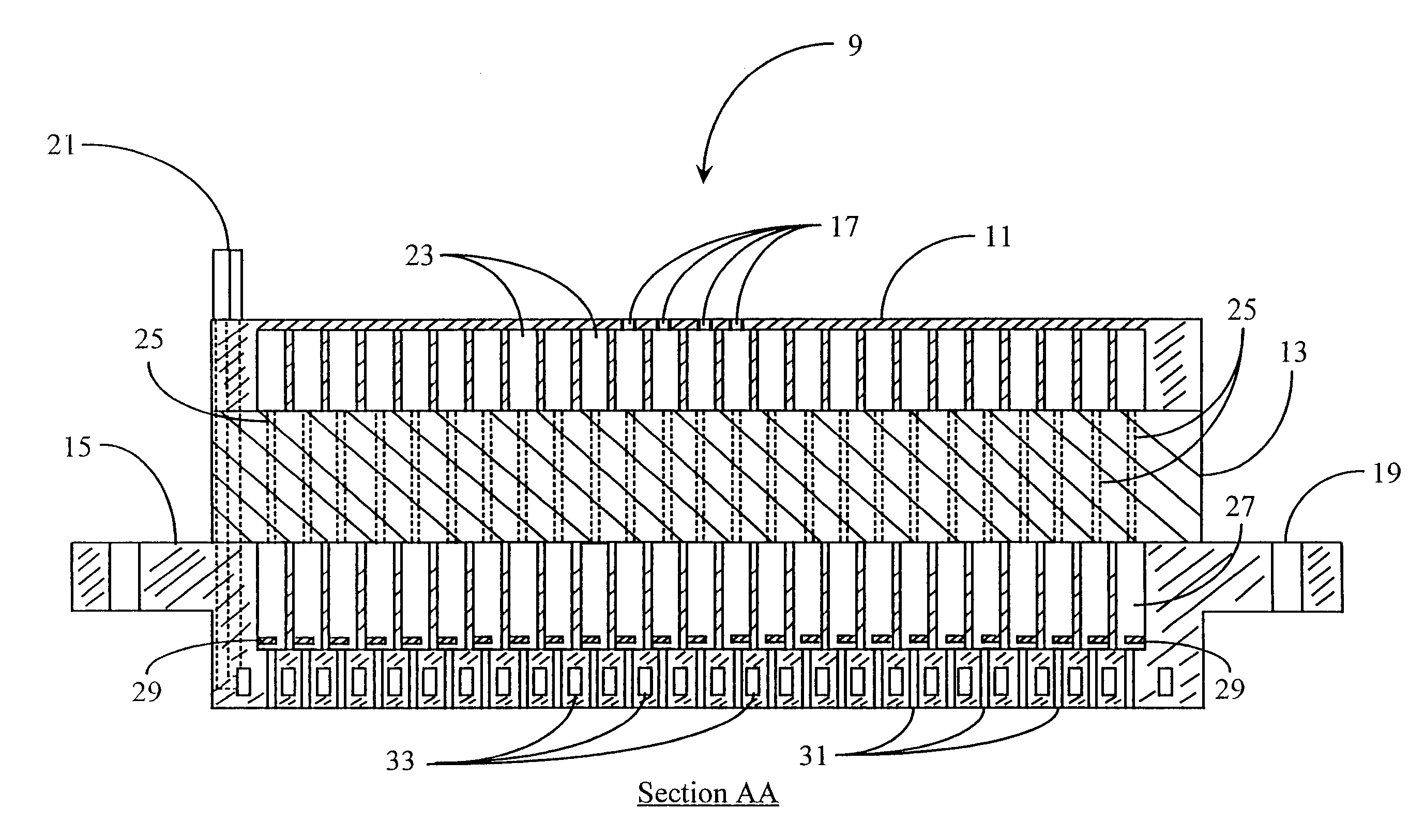
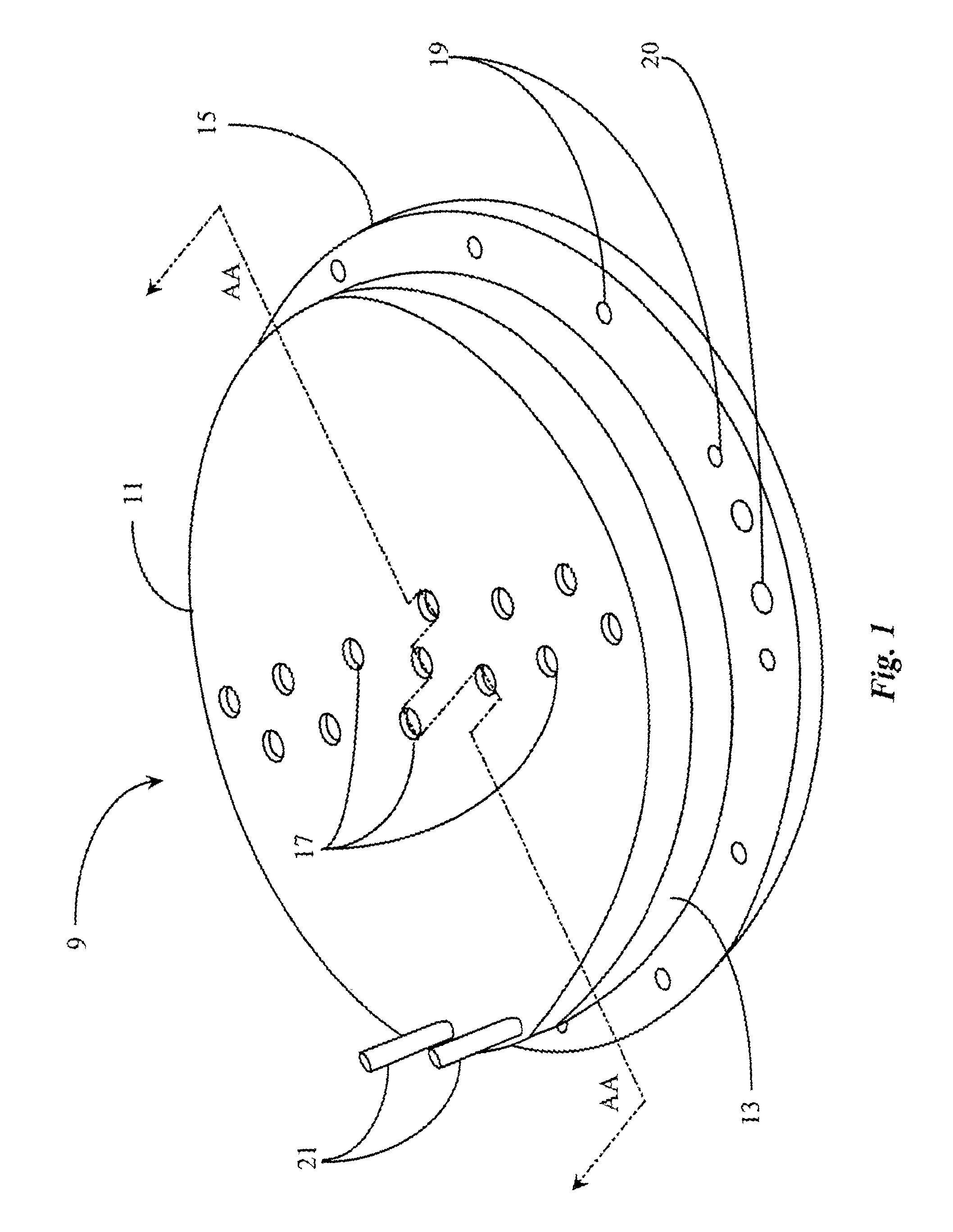
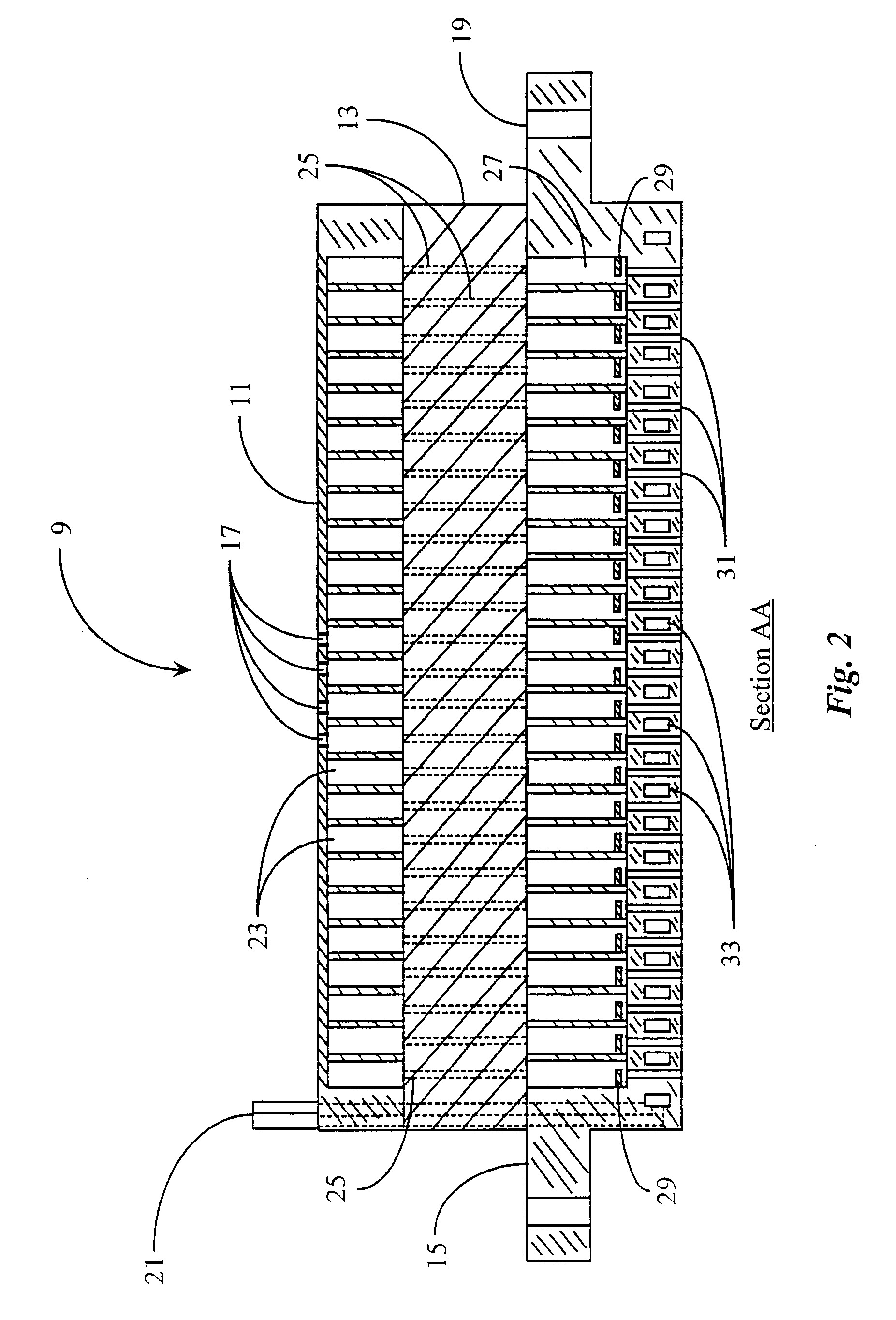
[0025]FIG. 1 is an isometric view of a multi-zone diffuser 9 according to an embodiment of the present invention. Diffuser 9 is adapted for delivering gas precursors and inert gases for the purpose of depositing films in CVD or CVD-variant processes.

[0026]Diffuser 9 is an assembly comprising in this embodiment three basic components, being an upper diffusion channel assembly...


PUM

PropertyMeasurementUnit
sizeaaaaaaaaaa
sizeaaaaaaaaaa
degrees of freedomaaaaaaaaaa

Abstract

A showerhead diffuser apparatus for a CVD process has a first channel region having first plural independent radially-concentric channels and individual gas supply ports from a first side of the apparatus to individual ones of the first channels, a second channel region having second plural independent radially-concentric channels and a pattern of diffusion passages from the second channels to a second side of the apparatus, and a transition region between the first channel region and the second channel region having at least one transition gas passage for communicating gas from each first channel in the first region to a corresponding second channel in the second region. The showerhead apparatus has a vacuum seal interface for mounting the showerhead apparatus to a CVD reactor chamber such that the first side and supply ports face away from the reactor chamber and the second side and the patterns of diffusion passages from the second channels open into the reactor chamber. In preferred embodiments the supply ports, transition passages, and diffusion passages into the chamber do not align, and there is a special plasma-quenching ring in each of the second channels preventing plasma ignition within the channels in the showerhead methods and systems using the showerhead are also taught.

Description

CROSS-REFERENCE TO RELATED DOCUMENTS[0001]The present application is a continuation application of patent application Ser. No. 10 / 335,404 entitled “Method and Apparatus for Providing Uniform Gas Delivery to Substrates in CVD and PECVD Processes,” which was filed on Dec. 30, 2002 now U.S. Pat. No. 6,616,766, which claims priority to patent application Ser. No. 09 / 939,272 filed Aug. 23, 2001, which claims priority to patent application Ser. No. 09 / 769,634 (U.S. Pat. No. 6,284,673) filed on Jan. 24, 2001, which claims priority to patent application Ser. No. 09 / 350,417 (U.S. Pat. No. 6,206,972) which was filed on Jul. 8, 1999, all of which are incorporated herein in their entirety.FIELD OF THE INVENTION[0002]The present invention is in the field of Chemical Vapor Deposition (CVD), including Plasma Enhanced Chemical Vapor Deposition (PECVD) and related processes, and pertains more particularly to methods and apparatus for controlling flux uniformity for gas delivery.BACKGROUND OF THE INV...

Claims


Application Information

Patent Timeline
Patent Type & Authority Patents(United States)
IPC IPC(8): H01L21/30B05B1/24C23C16/00C23C16/44C23C16/455H01J37/32
CPCC23C16/455H01J37/3244C23C16/45572C23C16/45565
Inventor DUNHAM, SCOTT WILLIAM
Owner EUGENUS INC
Why Eureka
Try Eureka