Impedance monitoring system and method

a technology of impedance monitoring and monitoring system, applied in the direction of resistance/reactance/impedence, instruments, greenhouse gas reduction, etc., can solve the problems of lens degradation, low measurement reproducibility of emission line intensity, and often hindered technique, so as to increase the signal-to-noise ratio

Inactive Publication Date: 2006-03-28
TOKYO ELECTRON LTD
View PDF11 Cites 27 Cited by
  • Summary
  • Abstract
  • Description
  • Claims
  • Application Information

AI Technical Summary

Problems solved by technology

However, this technique has some serious shortcomings, such as low measurement reproducibility of emission line intensity, and lens degradation.
However, this technique is often hindered by the small phase difference involved in the measurement.
However, this correlation method requires a large number of measurements for every individual system to obtain statistically averaged plasma characteristics.
There are other problems with known plasma measuring techniques.
However, this technique is problematic because the plasma reacts to the RF power signal, which can result in a change of the plasma state.
However, it can be difficult to obtain meaningful measurements when noise interferes with the low-amplitude RF signals.
Thus, it is usually rather difficult to determine the real part of the system impedance due to the large phase angle or nearly singular argument, and the difficulty of measuring thereof.
Moreover, the difficulty of extracting a small plasma resistance from a relatively large circuit resistance further exacerbates the problem.

Method used


Image

  • Impedance monitoring system and method
  • Impedance monitoring system and method
  • Impedance monitoring system and method

Examples


first embodiment

Method of Operation, First Embodiment

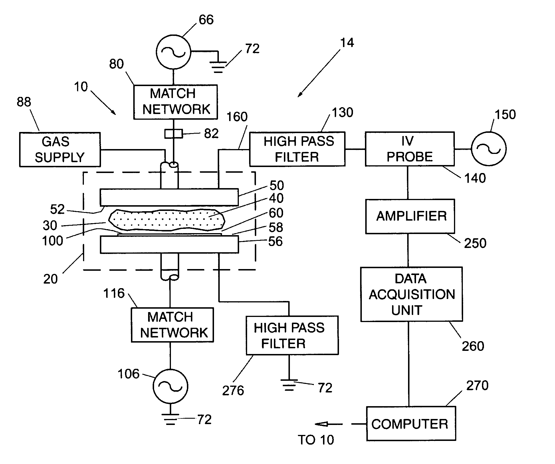
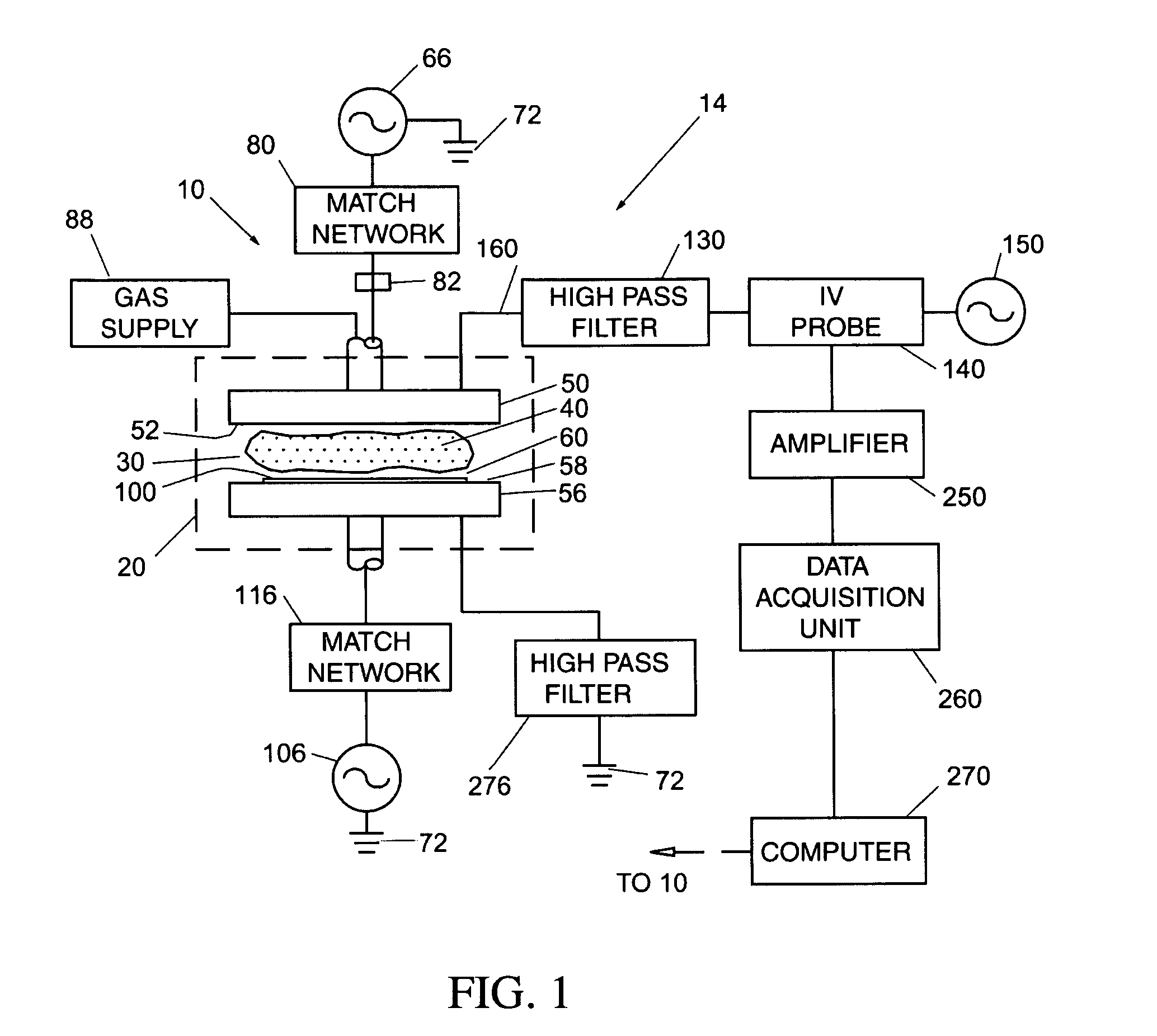
[0048]With reference now to FIG. 4 and flow diagram 600 therein, and also to FIG. 1, a method of measuring the impedance of plasma 40 in CC system 10 using impedance measurement system 14 and single-frequency sampling according to a first embodiment of the present invention is now described. In this first embodiment, high-frequency RF source 150 need only be capable of generating a single frequency, e.g., 150 MHz or 300 MHz.

[0049]In the first step 601, upper electrode power source 66 is turned off so that there is no plasma 40 formed in space 60 between upper and lower electrodes 50 and 56. In the next step 602, a high-frequency (e.g., 150 MHz) signal is generated by high-frequency source 150 and transmitted to upper electrode 50 through IV probe 140 and high-pass filter 130.

[0050]Next, in step 603, the current (I) and the voltage (V) passing through to upper electrode 50 via line 160 are measured along line 160 using IV probe 140. The raw output...

second embodiment

Method of Operation, Second Embodiment

[0061]In a second embodiment of the present invention, high-frequency RF source 150 is capable of generating signals at multiple frequencies, e.g., over a range from about 100 MHz to 300 MHz. In this second embodiment, a multiple frequency scanned probe signal is used to measure the system impedance more accurately than can be done with a single frequency probe signal. Particularly, the probe frequency can be scanned through the geometric resonance, at which the reactive impedance becomes vanishing small. Thus, measurement of the real part of the system impedance (i.e., the system resistance) is possible in this second embodiment.

[0062]With reference now to FIG. 5 and flow diagram 700 therein, and also again to FIG. 1, a method of measuring the impedance of plasma 40 in CC system 10 using impedance measurement system 14 and multiple-frequency sampling according to a second embodiment of the present invention is now described.

[0063]The first step...


PUM

PropertyMeasurementUnit
frequencyaaaaaaaaaa
frequencyaaaaaaaaaa
voltageaaaaaaaaaa

Abstract

An apparatus (14) for and method of measuring impedance in a capacitively coupled plasma reactor system (10). The apparatus includes a high-frequency RF source (150) in electrical communication with an upper electrode (50). A first high-pass filter (130) is arranged between the upper electrode and the high-frequency RF source, to block low-frequency, high-voltage signals from the electrode RF power source (66) from passing through to the impedance measuring circuit A current-voltage probe (140) is arranged between the high-frequency source and the high-pass filter, and is used to measure the current and voltage of the probe signal with and without the plasma present. An amplifier (250) is electrically connected to the current-voltage probe, and a data acquisition unit (260) is electrically connected to the amplifier. A second high-pass filter (276) is electrically connected to a lower electrode (56) and to ground, so as to complete the isolation of the high-frequency circuit of the impedance measurement apparatus from the low-frequency, high-voltage circuit of the capacitively coupled plasma reactor system. A method of measuring the plasma impedance using the apparatus of the present invention is also disclosed.

Description

CROSS-REFERENCE TO RELATED APPLICATIONS[0001]This application claims priority to International Application No. PCT / US02 / 05112, filed on Mar. 14, 2002; which claims priority to U.S. Provisional Application Ser. No. 60 / 276,106, filed Mar. 16, 2001. The entire contents of these applications is incorporated herein by reference.BACKGROUND OF THE INVENTION[0002]1. Field of the Invention[0003]The present invention relates to plasma reactor systems, and in particular relates to a method of and system for monitoring the impedance in a parallel-plate plasma reactor system.[0004]2. Discussion of the Background[0005]Ionized gas or “plasma” may be used during processing and fabrication of substrates (e.g., semiconductor devices, flat panel displays and other products requiring etching or deposition of materials). Plasma may be used to etch or remove material from or sputter or deposit material onto a semiconducting, conducting or insulating surface. Creating a plasma for use in manufacturing or ...

Claims


Application Information

Patent Timeline
Patent Type & Authority Patents(United States)
IPC IPC(8): G01R27/08G01N27/62H05H1/00G01R19/00G01R27/26H01J37/32H05H1/46
CPCG01R27/2641H01J37/32935H01J37/321H01J37/32183H01J37/32082G01R19/0061Y02E30/10
Inventor QUON, BILL H.
Owner TOKYO ELECTRON LTD
Why Eureka
Try Eureka