Display device

a display device and display technology, applied in the field of display devices, can solve the problems of low resolution, and inability to adjust the display size,

Inactive Publication Date: 2006-03-28
MINOLTA CO LTD
View PDF11 Cites 30 Cited by
  • Summary
  • Abstract
  • Description
  • Claims
  • Application Information

AI Technical Summary

Benefits of technology

[0022]It is an object of the present in...

Problems solved by technology

However, since some pixels of all the pixels of the image display element modulate the lights with respective wavelengths, resolution is low.
The second method should have a plurality of light sources and an optical system for guiding lights from the light sources from the same direction to the image display element, and thus the structure is rather complicated.
In order that the first method provides an image with the same resolution as that in the second method, it is necessary to use a liquid crystal display having a lot of pixels, but since heightening of density of the pixels is limited, enlarging of the liquid crystal display is inevitable.
In the case where the color image is provided by the second method, there arises a problem that irregular brightness and color shading on the lig...

Method used


Image

  • Display device
  • Display device
  • Display device

Examples


first embodiment

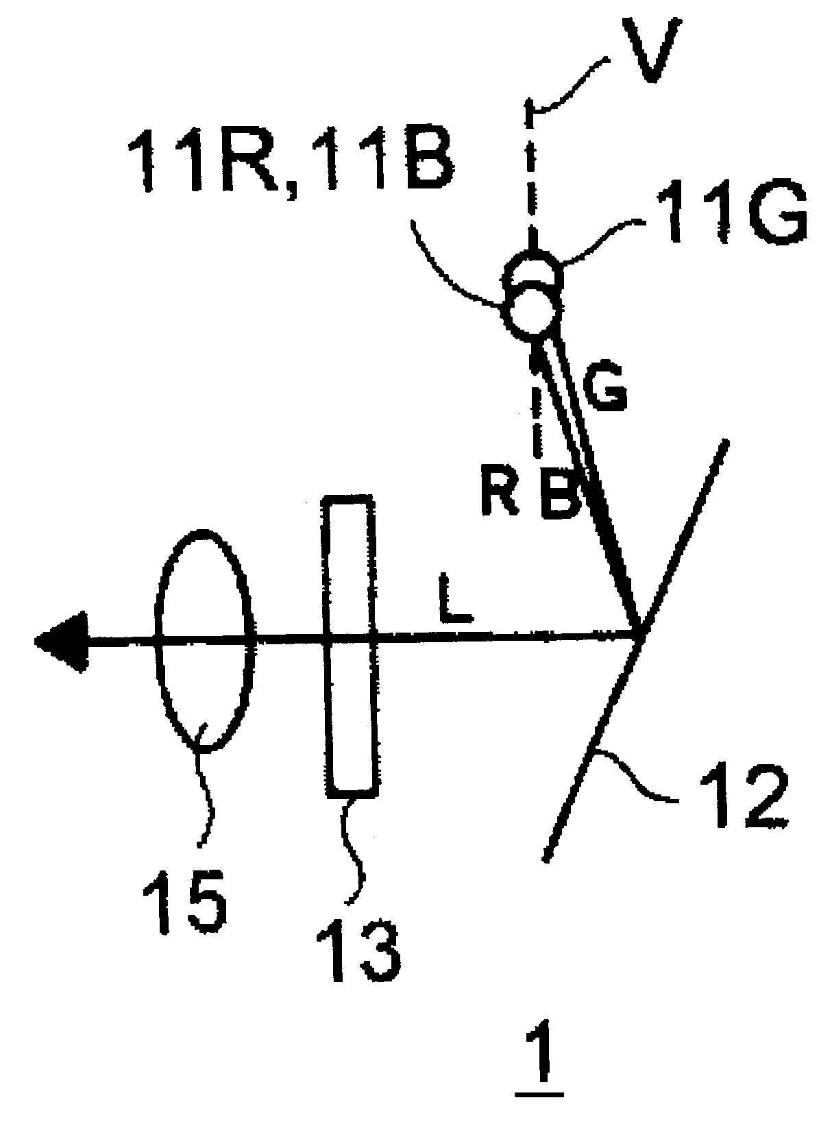
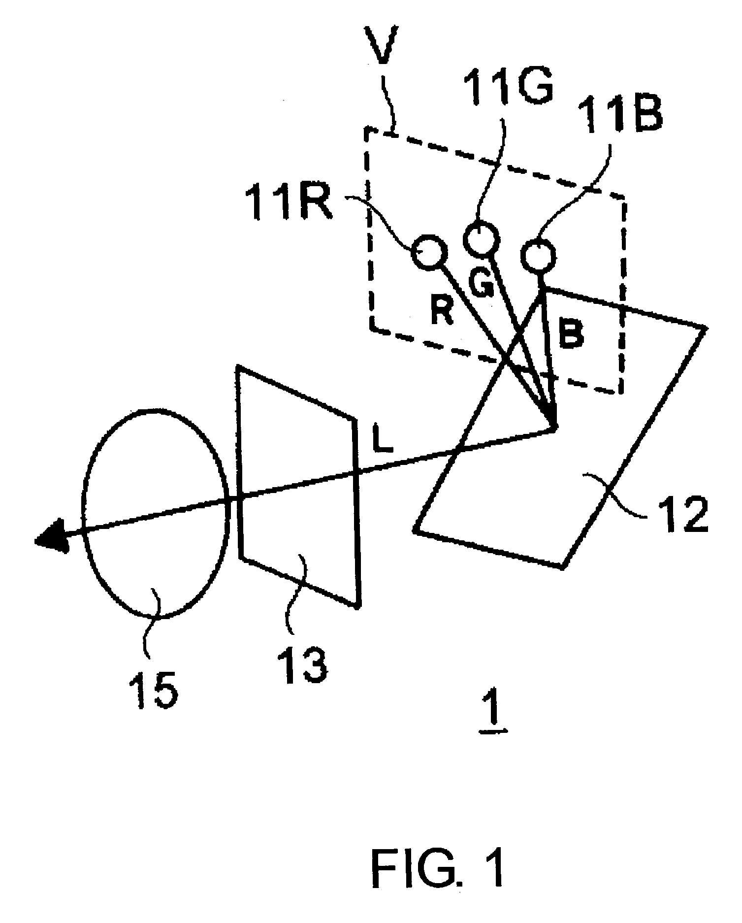
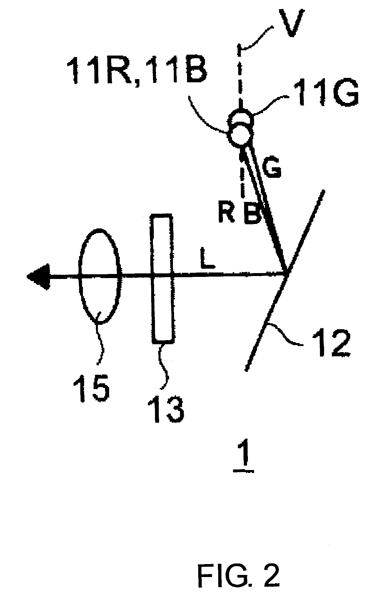
[0045]There will be explained below a display device according to embodiments of the present invention with reference to the drawings. An optical structure of a display device 1 is schematically shown in the perspective view of FIG. 1 and the side view of FIG. 2. The display device 1 is composed of three light emitting diodes 11R, 11G and 11B, a reflection type hologram element 12, a transmission type liquid crystal display 13 and an eyepiece optical system 15. The light emitting diodes 11R, 11G and 11B emit an R light, a G light and a B light, respectively. The lights emitted from the light emitting diodes 11R, 11G and 11B become a divergent pencil of lights, but FIGS. 1 and 2 show only a principal light of each light flux.

[0046]The reflection type hologram element 12 diffracts and reflect lights from the three light emitting diodes 11R, 11G and 11B so as to guide the diffracted and reflected lights to the liquid crystal display 13. The light emitting diodes 11R, 11G and 11B are a...

fifth embodiment

[0079]The display devices 1 through 4 according to the embodiments have the eyepiece optical system 15 and this system 15 is used before eyes but since it is small, it is suitable for a hand-held type and a head portion attachment type. FIG. 14 shows an appearance of a display system 5 in which the display devices 1 through 4 are of eyeglass head portion attachment type. A frame 52 which houses the light emitting diodes 11R, 11G and 11B, the hologram element 12 and the like are mounted to an upper edge of a transparent plate 51 corresponding to a spectacle lens, and the eyepiece optical system 15 is provided to a center of the transparent plate 51. Moreover, the frame 52 is connected with a cable 53 for giving an image signal, a control signal and the like from a controller, not shown.

[0080]FIG. 15 schematically shows the optical structure of the display system 5 exemplifying the case where the transmission type liquid crystal display 13 is used like the display device 1 according ...

sixth embodiment

[0082]An projection optical system is provided instead of the eyepiece optical system 15 of the display devices 1 through 4 so that a projection type display device for forming an enlarged real image on a screen can be provided. An appearance of the projection type display device 6 is shown in a side view of FIG. 16. The display device 6 is composed of a folding type screen 61 and a frame 62. The frame 62 houses the components explained in the above embodiments such as the light emitting diodes 11R, 11G and 11B, the hologram element 12 and the liquid crystal display 13 or 14, and a projection type optical system. As the screen 61, a diffusing plate, a reflection type hologram element and the like can be used.

[0083]The display devices 1 through 6 according to the embodiments use the light emitting diodes as light sources, but can use another light emitting elements such as a laser diode as a light source. Moreover, instead that the light emitting elements are provided in the vicinit...


PUM


Abstract

A display device has a plurality of light emitting elements for emitting lights, a display element for modulating the light emitting from the plurality of light emitting elements so as to convert it to an image light showing an optical image, a reflection type hologram element, having a positive optical power with respect to the lights from the plural light emitting elements, for diffracting and reflecting the lights from the plural light emitting elements to approximately one direction so as to guide the diffracted and reflected lights to the display element; and an enlarging optical system for forming an enlarged image of the optical image converted by the lights from the image display element. The plural light emitting elements are positioned in a plane approximately vertical to an optical path of the lights diffracted and reflected by the hologram element. The hologram element is tilted to a direction facing the plural light emitting elements with respect to the optical path of the lights diffracted and reflected by the hologram element.

Description

RELATED APPLICATION[0001]This application is based on Application No. 2002-47411 filed in Japan, the content of which is hereby incorporated by reference.BACKGROUND OF THE INVENTION[0002]1. Field of the Invention[0003]The present invention relates to a display device which has an image display element which modulates an illumination light to convert it into a light showing an image, and particularly relates to its illumination optical system.[0004]2. Description of the Prior Art[0005]A display device, which has a liquid crystal display for modulating a given illumination light to convert it into a light showing an image and an eyepiece optical system for guiding the light from the liquid crystal display to an eye so as to provide a virtual image of the image, are used a lot as small image providing means. Such a display device optically conjugates a light source surface emitting the illumination light and the eye of an observer so as to provide a bright image. Moreover, in the case ...

Claims


Application Information

Patent Timeline
IPC IPC(8): G02F1/1335G02F1/13G02B5/32G02B27/00G02B27/01G02B27/02G02B27/28G02F1/13357G03B21/00H04N5/64H04N5/66H04N5/74
CPCG02B5/203G02B5/32G02B27/0172G02F1/133621G02B2027/0118G02F2203/34G02B2027/0178G02F2001/133622G02B2027/0174G02F1/133622
Inventor ENDO, TAKESHIKASAI, ICHIRO
Owner MINOLTA CO LTD
Why Eureka
Try Eureka