Transponder and wavelength division-multiplexing optical transmission equipment

a technology of optical transmission equipment and wavelength division, applied in the field of transponder and wavelength divisionmultiplexing optical transmission equipment, can solve the problems of reducing transmission quality, unable to reproduce signal degeneration, and unable to guarantee regeneration timing

Inactive Publication Date: 2006-03-28
HITACHI LTD
View PDF4 Cites 15 Cited by
  • Summary
  • Abstract
  • Description
  • Claims
  • Application Information

AI Technical Summary

Benefits of technology

[0007]It is an objective of certain embodiments of the present invention to provide a transponder and wavelength division-mul...

Problems solved by technology

2R regeneration does not reproduce any degeneration of signal timing and easily satisfies the digital signal transparency requirement.
On the other hand, it does not guarantee any regeneration timing.
This regeneration can produce temporal fluctuations in the signals that are regenerated and relayed over the network, which res...

Method used


Image

  • Transponder and wavelength division-multiplexing optical transmission equipment
  • Transponder and wavelength division-multiplexing optical transmission equipment
  • Transponder and wavelength division-multiplexing optical transmission equipment

Examples


first embodiment

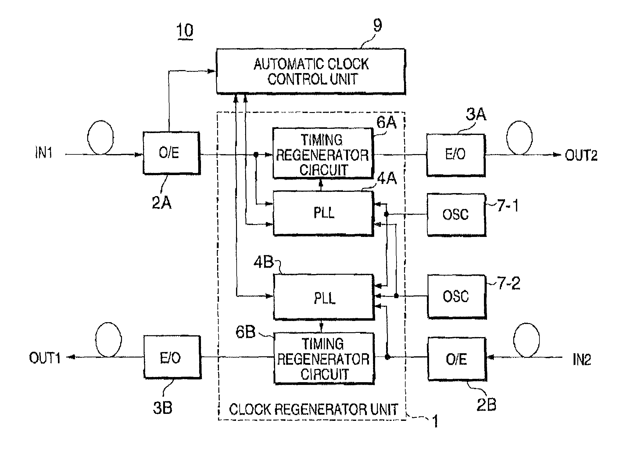
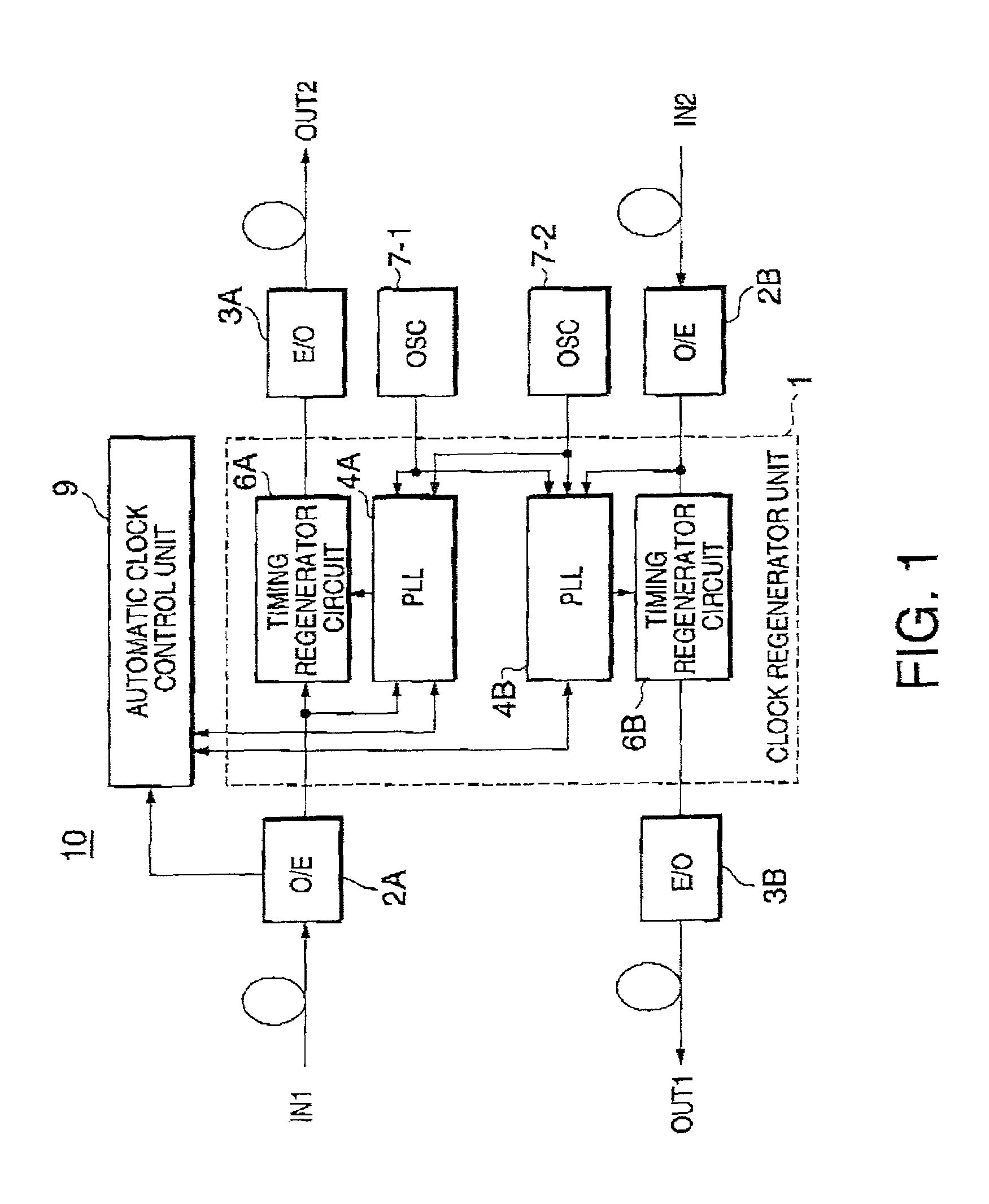
[0031]FIG. 3 is a diagram illustrating the clock regenerator unit 1 that was shown in FIG. 1.

[0032]Following is a description of the configuration and operation of the PLL circuit 4A for the digital signals that travel from the client equipment to the wavelength division-multiplexing unit. Since the description of PLL circuit 4B of a similar configuration for the digital signals traveling from the wavelength division-multiplexing node apparatus to the client equipment would be the same as that of PLL circuit 4A, it is not repeated.

[0033]When a high-level optical input signal beyond a predetermined threshold value is detected in the O / E converter 2A, a detection signal S2 indicating the detection of a transmission signal is input into the auto-clock controller 9, which commences the automatic timing regeneration control. The PLL circuit 4A includes a voltage control oscillator (VCO) 41, a first frequency divider 42 with a variable division ratio that divides the clock signals generat...


PUM


Abstract

A wavelength converter and a wavelength division-multiplexing optical communication apparatus automatically generate clock signals of a specified frequency that match send/receive digital signals and regenerates timing for the send/receive digital signals. The wavelength converter includes: optical/electrical signal converters (2A, 2B) that convert input optical signals into electric digital signals; clock generator circuits (4A, 4B) that automatically identify the transmission mode for digital signals and generate phase-synchronized clocks of a specified frequency that match the signal transmission mode; timing regeneration circuits (6A, 6B) that regenerate clock timing for the digital signals based upon the phase-synchronized clocks from the clock generator circuits; and electric/optical converters (3A, 3B) that convert the digital signals from the timing regeneration circuits into optical signals of a specified wavelength.

Description

BACKGROUND OF THE INVENTION[0001]The present invention is directed to a transponder and wavelength division-multiplexing optical transmission equipment for optical communication. More specifically, it relates to a transponder and wavelength division-multiplexing optical transmission equipment for transmitting wavelength division-multiplexed digital signals.[0002]The explosive growth of the Internet has required various modes of data communication services over communications networks. Communication vendors, for example, are required to transmit various types of signals with different signal transmission rates, transmission formats, and protocols over a single optical network. Signal transmission modes for digital signals that are transmitted over wavelength division-multiplexing networks include, for example, Synchronous Digital Hierarchy (SDH), Synchronous Optical NETwork (SONET), Fast Ethernet (100Base FX), Giga Ethernet (1000Base SX, LX), and Fibre Channel (1.06 GBd, 2.12 GBd). I...

Claims


Application Information

Patent Timeline
IPC IPC(8): H04B10/02H04J14/08H03L7/087H03L7/095H03L7/197H04B10/29H04B10/299H04J3/06H04J14/00H04J14/02H04L7/033H04Q11/04
CPCH03L7/087H03L7/197H04B10/29H03L7/095H04L7/033H04J3/0688H04J14/02
Inventor SAKANO, SHINJIISHII, RYUJIYAMADA, YOSHINORI
Owner HITACHI LTD
Why Eureka
Try Eureka