Device for the determination of blood clotting by capacitance or resistance

a capacitance or resistance technology, applied in the direction of liquid/fluent solid measurement, level indicators by physical variable measurement, engine lubrication, etc., can solve the problem of excessive and dangerously prolonged clotting time in another patient, difficult adjustment of the amount of bioavailable drugs in the body, and complicated determination of dosing regimen

Inactive Publication Date: 2006-04-04
ORGENICS BOISENSORS
View PDF26 Cites 64 Cited by
  • Summary
  • Abstract
  • Description
  • Claims
  • Application Information

AI Technical Summary

Benefits of technology

[0014]It is one object of the present invention to provide a novel device and method for the determina

Problems solved by technology

A dosing regimen which does not increase clotting time in one patient might result in an excessively and dangerously prolonged clotting time in another patient.
The determination of dosing regimen is further complicated by the pharmacological properties of some anti-coagulant drugs, such as warfarin, which may remain highly bound to proteins in the blood, so that the amount of bioavailable drug in the body may be difficult to adjust.
Unfortunately, currently clotting time can only be measured in a clinical laboratory setting by a clinical laboratory technician.
All of these devices suffer from the drawback of being either complex to operate or complex to construct.
Such concentration may not be difficult for a trained laboratory technician, but places an excessive burden on the lay patient who wishes to measure clotting time in a home testing environment.
WO 96/00395, as yet no such device is available for the home testing market.
The alternative form for optical analysis, in which a beam of light is transmitted from a light source through the blood sample to a photodetector, suffers from the drawback of being too complex and expensive to manufacture as a home testing device.
Such a device would also require careful maintenance and calibration on a regular basis, which also places an excessive burden on the lay patient for home testing.
Thus, automated optical analysis is not suitable for the home testing environment.
However, this device required complex, delicate and sensitive laboratory equipment to measure the impedance of the sample, which would not be suitable for home testing.
Furthermore, although the device was first disclosed more than twenty years ago, no commercially available equivalent device has been produced for the laboratory or for the home testing environment, an indication of the technical difficulties inherent in the design, production and operation of such a device.
Thus, the measurement of electrical impedance

Method used


Image

  • Device for the determination of blood clotting by capacitance or resistance
  • Device for the determination of blood clotting by capacitance or resistance
  • Device for the determination of blood clotting by capacitance or resistance

Examples


example 1

Construction and Testing of a Clotting Time Device

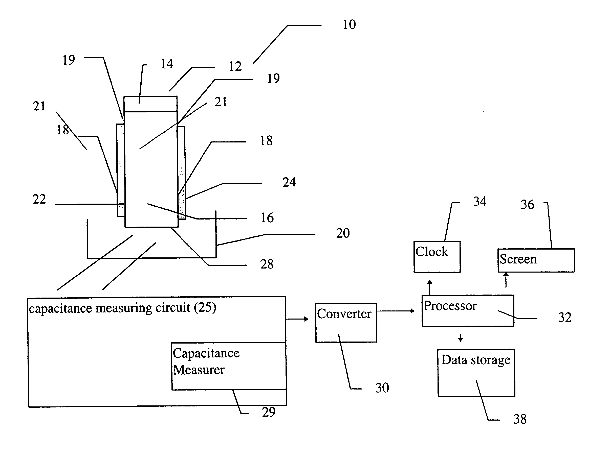
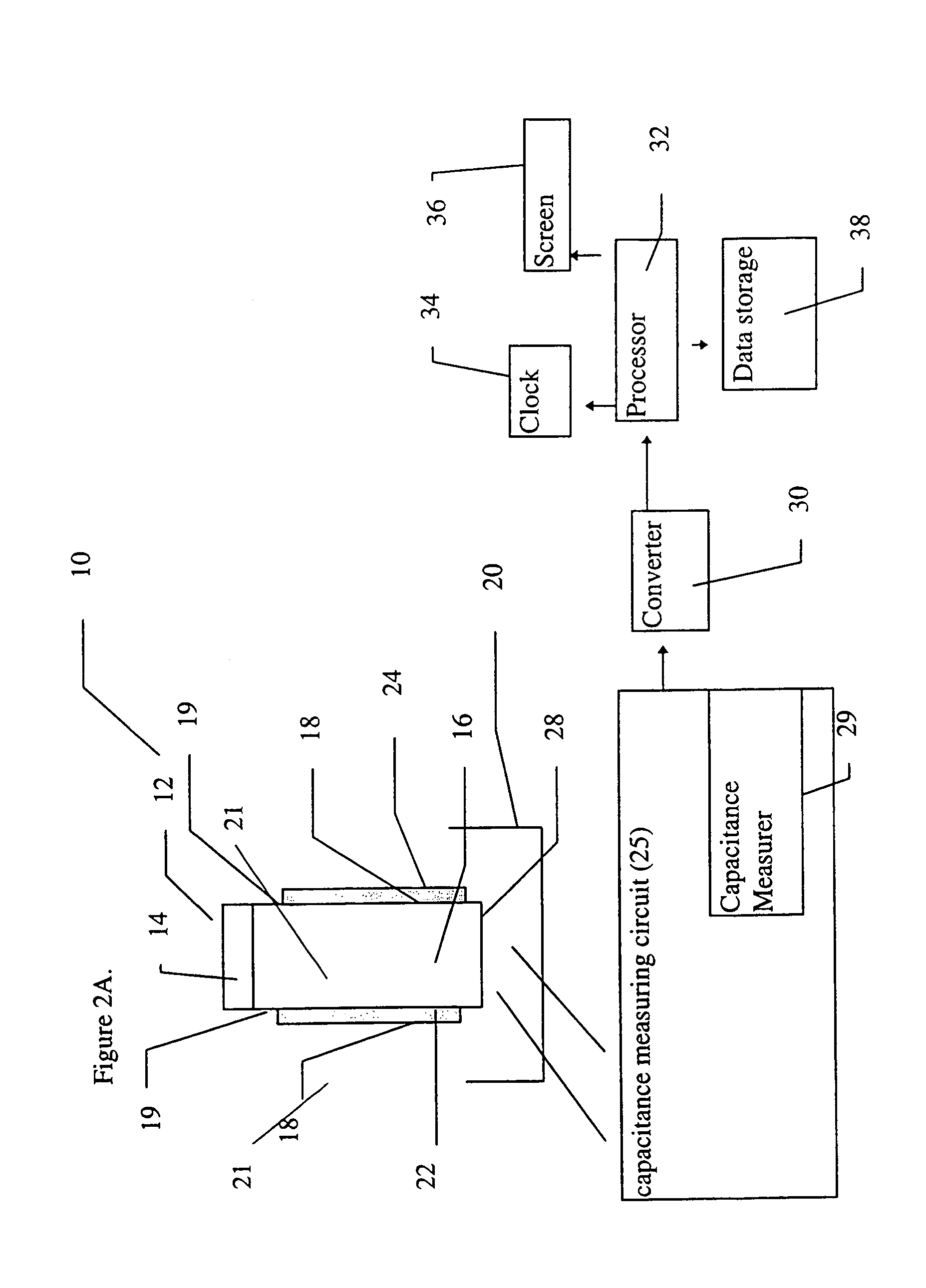
[0126]The device, including the sensor, was constructed according to the first example of this embodiment of the device of the present invention, as shown in FIG. 5A. The sensor was constructed from a flat plastic base card, by building an approximately 1.5 mm wide and approximately 20 mm long capillary channel over the two conductive carbon tracks. The sides of the channel were built from double sided adhesive tape, about 200 microns deep. The channel was covered with a section of transparent polyester film. The arrangement was designed to permit a reference portion of a five microliter blood sample to travel along the entire length of the capillary channel, while a second portion of the same sample remains at the sample origin, thus preventing limitation of measurement by the sample size.

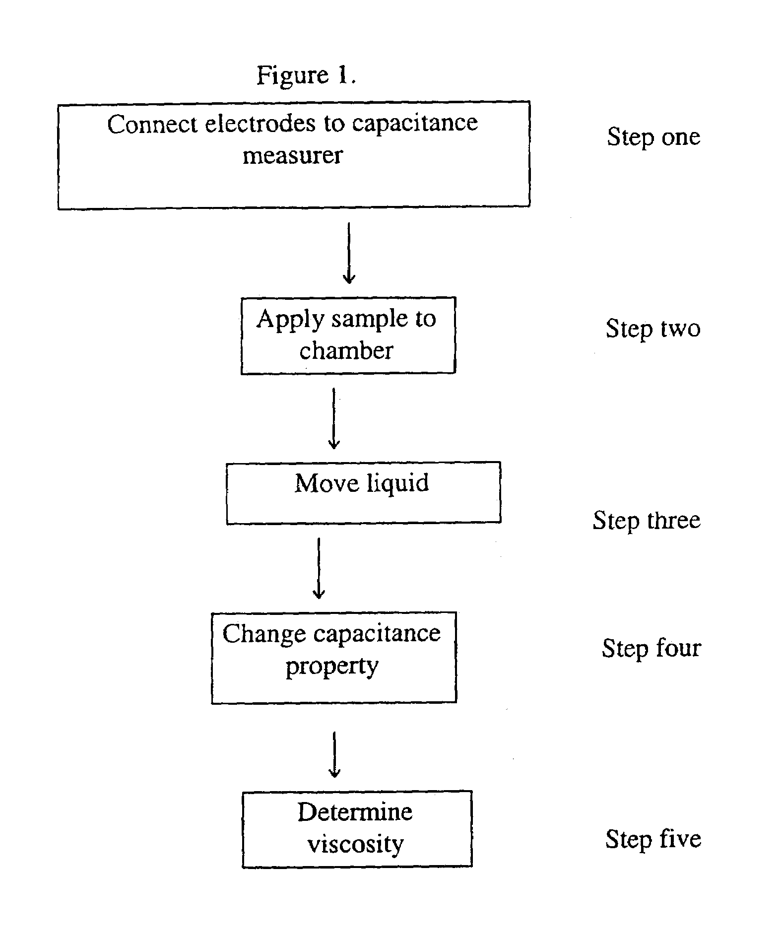
[0127]The electrodes were then attached to a standard voltage generating device, and the resulting current was then measured by a standard device ...

example 2

Construction and Testing of a Clotting Time Device with Dried Reagents

[0132]An exemplary device of the present invention was also constructed according to the first embodiment of the device of the present invention, as shown in FIG. 5A. In this case, however, coagulation reagents (Sigma Chemical Co) were dried in one area of the sensor. It should be noted that this device was also intended as an example for experimental testing only and was not meant to be limiting in any way.

[0133]FIG. 7A shows the variation of the current (micro-amperes) over time (seconds) for three different blood samples from patients undergoing anticoagulant therapy. These samples had different clotting times, which were measured as prothrombin time. Prothrombin time was determined both by the sensor, as shown in the graph, and with a standard reference method, employing an ACL1000 instrument. The clotting times obtained with the standard instrument are shown inside rectangles, attached to each of the current ...

example 3

Construction and Testing of a Clotting Time Device with Dried Reagents

[0137]An exemplary device of the present invention was also constructed according to the first embodiment of the device of the present invention, as shown in FIG. 5A. However, as further detailed below, certain modifications were made to the device. In particular, the carbon electrodes were subjected to a pretreatment, and a particular formulation of coagulation reagents was dried onto the sample area of the sensor of the present invention. It should be noted that this device was also intended as an example for experimental testing only and was not meant to be limiting in any way.

[0138]The preparation of this exemplary device according to the present invention was as follows. First, the carbon electrodes were cut and then pretreated by soaking in a buffer containing 0.1 M Na2CO3, 10 mg / ml BSA and 0.1% Tween-20 for 10 minutes at room temperature. Next, the electrodes were washed four times by dipping in distilled w...


PUM


Abstract

A sensor device (10) and a method for measuring a viscosity of a sample of a liquid. The sensor features a chamber (12) for receiving the sample of the liquid, two electrodes (18) disposed either on the surfaces of the chamber, but possibly isolated from contacting the sample, or electrodes located externally to the chamber, and a capacitance measuring circuit (25). The sensor is used by connecting to a measurer for determining a capacitance on the electrodes, such that the capacitance directly reflects a volume occupied by the sample of the liquid. Preferably, the liquid is blood and the capacitance is used to determine the clotting time of the blood. Also preferably, a cover for the chamber is provided with at least one aperture, which more preferably is a mesh. Alternatively, an electrical property such as the amplitude of current passed through the sample is used to determine clotting time. Also preferably, the time period required for the maximum capacitance to be reached could be measured. Alternatively, the capacitance could be measured after a fixed time period (34) had elapsed. Also alternatively, the time period required for the maximum current to be reached could be measured, or the amount of current could be measured after a fixed time period had elapsed. In preferred embodiments of the present invention, a kit for measuring the clotting time of blood is provided. In other preferred embodiments of the present invention, methods are provided for using the kit and device of the present invention.

Description

FIELD AND BACKGROUND OF THE INVENTION[0001]The present invention relates to a device and method for determining viscosity of a liquid sample by capacitance or resistance, and, in particular, to a device and method for analyzing clotting of a blood specimen by a patient in a home testing environment, substantially without the need for intervention by highly trained clinical laboratory technicians or other technical medical personnel.[0002]Clotting time is the amount of time required for a blood sample from a patient to clot. The determination of clotting time is important for patients who are receiving anti-coagulant therapy, such as those patients taking the drug warfarin, for example. The dosing regimen for such drugs must be determined for each individual patient, and then adjusted according to the clotting time. A dosing regimen which does not increase clotting time in one patient might result in an excessively and dangerously prolonged clotting time in another patient. The deter...

Claims


Application Information

Patent Timeline
IPC IPC(8): G01N11/00
CPCG01N11/04G01N33/491G01N2011/0066
Inventor ROSEMBERG, YOSSEFFISH, FALKLEVI, RAPHAEL
Owner ORGENICS BOISENSORS
Why Eureka
Try Eureka