
Diaphragm valve with reliability enhancements for atomic layer deposition

Inactive Publication Date: 2006-04-04
BENEQ OY
View PDF37 Cites 204 Cited by
  • Summary
  • Abstract
  • Description
  • Claims
  • Application Information

AI Technical Summary

Benefits of technology

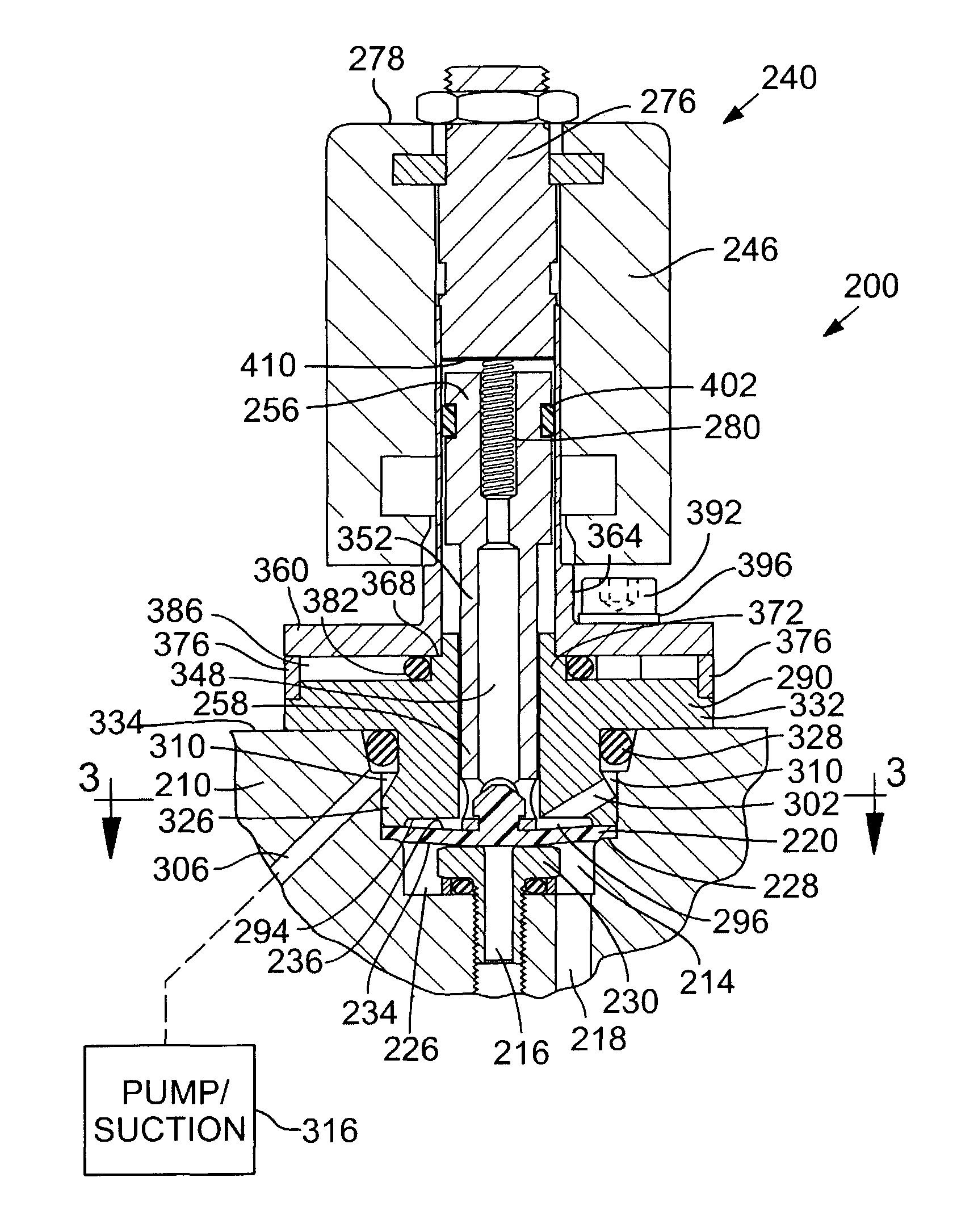
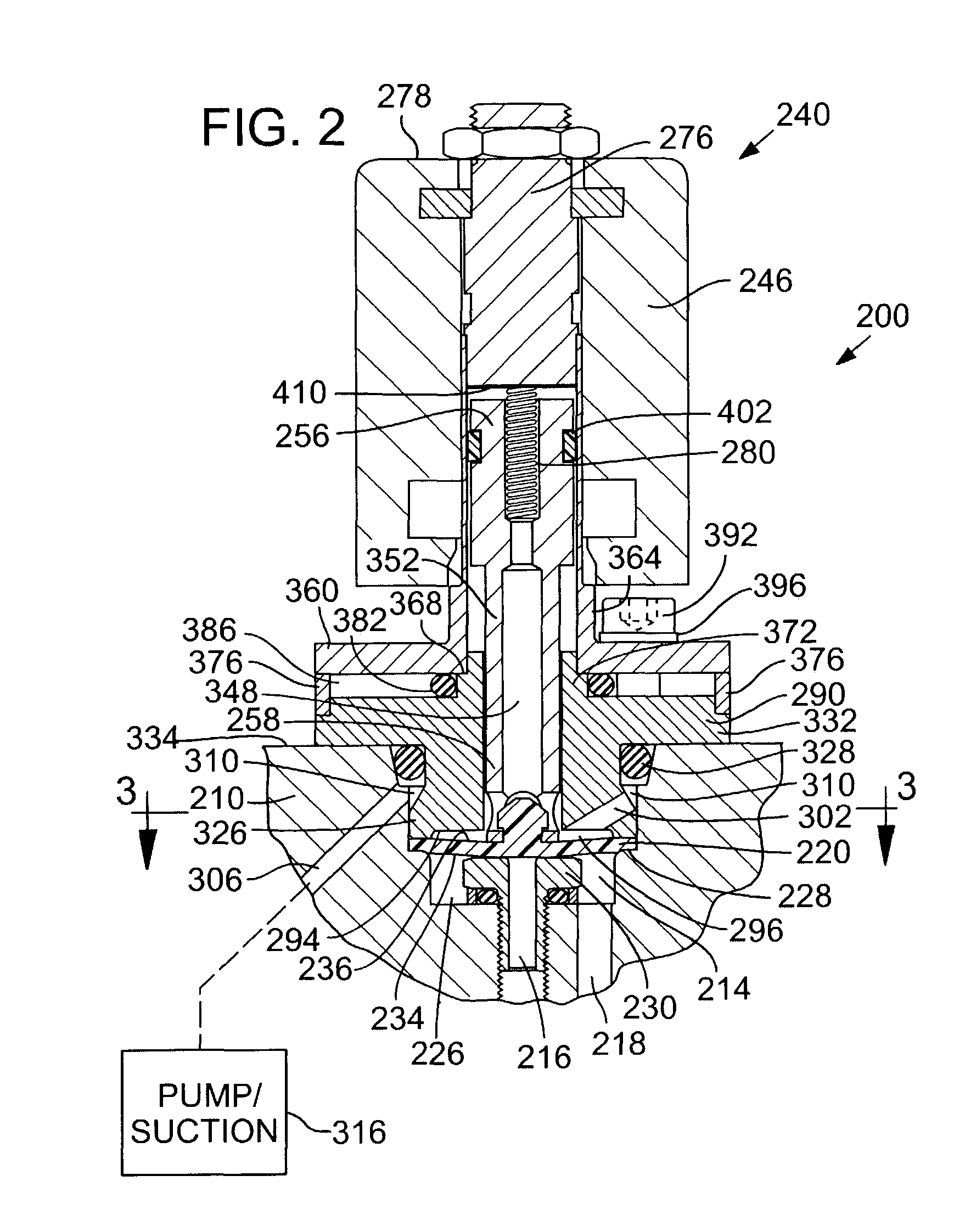
[0012]In accordance with the invention, a shut-off type diaphragm valve includes a rigid valve seat surrounding an inlet or an outlet of the valve passage. A flexible diaphragm is positioned adjacent the valve passage opposite the valve seat and is operable in response to an actuation force to flex between an open position, wherein a medium can flow through the valve passage, and a closed position in which a first side of the diaphragm is pressed against the valve seat to prevent the flow of medium through the valve passage. The actuation force may be applied by a solenoid or hydraulic actuator, for example. The valve seat includes an annular seating surface that extends radially from the inlet and is sized and shaped to contact a substantial portion of the first side of the diaphragm when the diaphragm is flexed to the closed position, thereby facilitating heat transfer between the valve seat and the diaphragm. Improved heat transfer between the valve seat and the diaphragm can counteract dissipative cooling of the diaphragm (to the environment), thereby inhibiting the medium from condensing or freezing in the valve passage.
[0013]When an elastomeric diaphragm is used the annular seating surface is preferably devoid of sharp features, to prevent shearing of the diaphragm when pressed against the valve seat. The annular seating surface may also be made sufficiently large so that the diaphragm, when closed, will not contact an outer peripheral edge of the seating surface. When a plastic diaphragm is used, the valve seat may include a ring-shaped seating ridge that extends from the seating surface high enough to cause localized permanent deformation of the first side of the diaphragm when closed, while being short enough to allow a substantial portion of the diaphragm to contact the annular seating surface. In some embodiments, the seating surface is polished to improve heat transfer from the valve seat to the diaphragm, when closed. A spacer ring may also be interposed between the valve seat and the valve body to establish an axial position of the seating surface relative to the valve body, for more accurate control of valve seating force.

Problems solved by technology

Even at such high temperatures and low operating pressures, pulses of precursor vapors are not delta functions, meaning they have a substantial rise and decay time.
If substantial amounts of the different precursor vapors are present in the reaction space at the same time, then non-ALD growth can occur, which can generate particles or non-uniform film thickness.
However, the increased volume of the reaction space in a batch processing system may require increased precursor pulse durations and purge intervals.
Long purge intervals increase processing time, which can substantially reduce the overall efficiency of an ALD reactor.
However, solenoid actuators generate heat when electric current is applied and, like hydraulic and pneumatic valves, solenoid actuated valves can fail when exposed to the high temperatures required for maintaining some precursor materials in vapor form.
Heat can degrade the insulation around the solenoid windings, resulting in electrical shorting between windings and failure of the solenoid coil.
Condensation and buildup of precursor material on the diaphragm and valve seat can cause the valve to leak or clog, leading to undesirable non-ALD growth and particles in the reaction chamber.
Heat dissipation through the valve can result in cooling of the flow path and the associated condensation problems discussed above.
However, heating the flow path may tend to contribute to overheating of the actuators in conventional diaphragm valves.

Method used


Image

  • Diaphragm valve with reliability enhancements for atomic layer deposition
  • Diaphragm valve with reliability enhancements for atomic layer deposition
  • Diaphragm valve with reliability enhancements for atomic layer deposition

Examples


Embodiment Construction

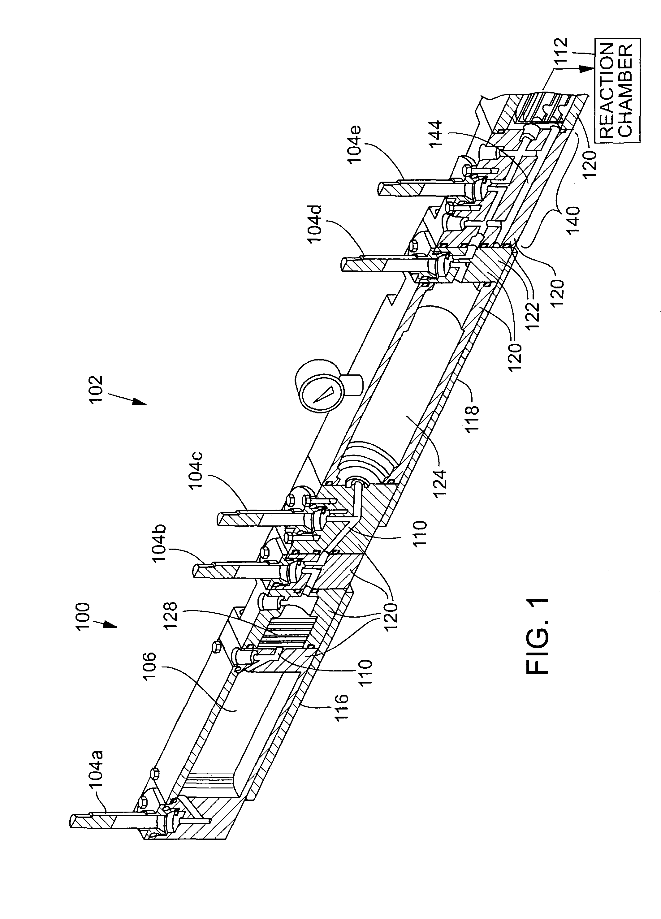
[0020]FIG. 1 is an isometric section view of a precursor material delivery system 100 of an ALD reactor 102, which comprises an exemplary environment of use for valves 104a–104e, in accordance with a first preferred embodiment. With reference to FIG. 1, a supply of precursor material is stored in a precursor container 106, where it is heated and vaporized before flowing through a flow path 110 of the precursor material delivery system 100 (generally from left to right in FIG. 1) and into a reaction chamber 112. ALD reactor 102 will typically have two or more precursor material delivery systems 100 connected to reaction chamber 112. Precursor material delivery system 100 includes electric heaters 116 and 118 for heating precursor materials in the flow path 110. Valves 104a–104e are used to control the flow of precursor material and regulate pressure of the precursor vapor at different stages in precursor material delivery system 100.

[0021]Precursor material delivery system 100 prefer...


PUM


Abstract

A shut-off type diaphragm valve adapted for use in an atomic layer deposition system includes a valve seat having an annular seating surface that surrounds an inlet of the valve and extends radially therefrom. The seating surface contacts a substantial portion of the first side of a flexible diaphragm when the diaphragm is closed, to facilitate heat transfer and counteract dissipative cooling of the diaphragm, thereby inhibiting condensation of a medium flowing through the valve passage. The seating surface is preferably flat and smooth, to prevent shearing of an elastomeric diaphragm. For a plastic diaphragm, a ring-shaped seating ridge may extend from the seating surface to cause localized permanent deformation of the diaphragm and enhanced sealing, while still allowing a substantial portion of the diaphragm to contact the seating surface for enhanced heat transfer. Valve speed enhancements and other reliability enhancing features are also described.

Description

TECHNICAL FIELD[0001]The present invention relates to a diaphragm valve that is particularly useful in high-temperature thin film deposition systems and equipment.BACKGROUND OF THE INVENTION[0002]Atomic Layer Deposition (“ALD”), also known as Atomic Layer Epitaxy (“ALE”), is a method of depositing thin films onto a substrate that involves sequential and alternating self-saturating surface reactions. The ALD process is described in U.S. Pat. No. 4,058,430 of Suntola et al., which is incorporated herein by reference. ALD offers several benefits over other thin film deposition methods, such as Physical Vapor Deposition (“PVD”) (e.g., evaporation or sputtering) and Chemical Vapor Deposition (“CVD”), which are well known to those skilled in the art, as described in Atomic Layer Epitaxy (T. Suntola and M. Simpson, eds., Blackie and Son Ltd., Glasgow, 1990). ALD methods have been proposed for use in depositing thin films on semiconductor wafer substrates, to achieve desired step coverage a...

Claims


Application Information

Patent Timeline
IPC IPC(8): F16K49/00F16K31/126F16K7/14F16K31/06
CPCF16K7/14F16K49/002F16K31/0693F16K31/06Y10T137/6606
Inventor MAULA, JARMO ILMARILESKINEN, HANNULANG, TEEMUKUOSMANEN, PEKKAHARKONEN, KARIAITCHISON, BRADLEY J.
Owner BENEQ OY
Learn More