Dynamic road marking system and road segment provided with said system

a road marking system and dynamic technology, applied in the direction of traffic signals, roads, instruments, etc., can solve the problem that the road marking system cannot be used to influence the flow of traffic, and achieve the effects of convenient replacement, low cost, and efficient use of ligh

Inactive Publication Date: 2006-04-04
KONINKLIJKE PHILIPS ELECTRONICS NV
View PDF12 Cites 41 Cited by
  • Summary
  • Abstract
  • Description
  • Claims
  • Application Information

AI Technical Summary

Benefits of technology

[0033]As an alternative light source for use in the road marking system, use can very suitably be made of an end portion of an optical fiber. This has the advantage that the light emitted by the light source is generated in a light generator at a distance from the road marking unit and transferred from the light generator to the light source by means of optical fibers. The light generator may comprise a light source accommodated in the housing, for example a semiconductor light source such as a light-emitting diode, or a discharge lamp such as a mercury discharge lamp. In an attractive variant of this embodiment, the light generator comprises a first end of at least one light guide, which light guide is optically coupled, at a second, opposite end, to the light source in the road marking unit. The light source in the light generator is preferably arranged at a distance from the road marking unit so that said light source can be readily replaced, for example at the end of its service life. An advantage of employing optical light guides is that the use of optical fibers results in a very efficient use of light, which entails no, or at least very little, luminous pollution. Luminous pollution is to be taken to mean the loss of light caused by the fact that areas are illuminated at locations where illumination is not necessary and/or undesirable. An advantage of the use of optical light guides with respect to the use of light emitting diodes is that in the case of optical fibers, no electric voltages and currents have to be fed to the light source via the road surface. This results in increased traffic safety. Also in the case of accidents and other calamities, the risk of an electric voltage flashover or a short-

Problems solved by technology

A problem with these methods relates to indicating, in a flexible manner, the direction of the desired flow of traffic for a specific lane, or to changing the arrangement of the traffic route in a

Method used


Image

  • Dynamic road marking system and road segment provided with said system
  • Dynamic road marking system and road segment provided with said system
  • Dynamic road marking system and road segment provided with said system

Examples


Embodiment Construction

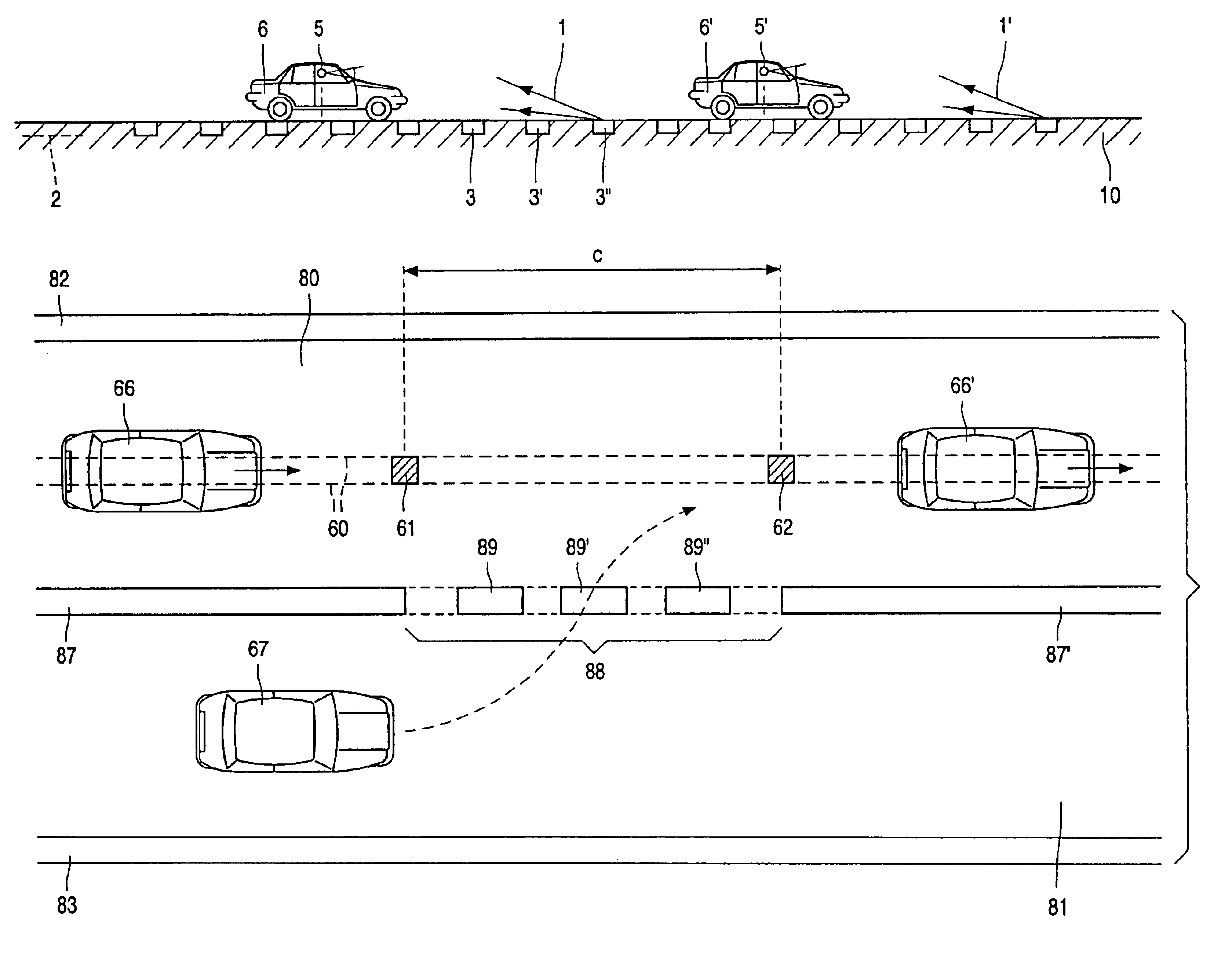
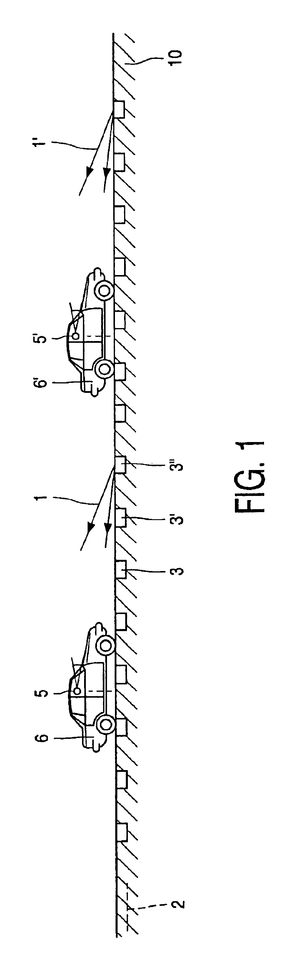
[0052]FIG. 1 is a cross-sectional view of a dynamic road marking system for influencing a flow of traffic consisting of vehicles 6, 6′, . . . traveling over a roadway 10. The road marking system comprises a plurality of road marking units 3; 3′, 3″, . . . . Each one of said road marking units 3, 3′, 3″, . . . is provided with a light source (not shown in FIG. 1) for emitting light in the direction of a driver 5, 5′, . . . of one of the vehicles 6, 6′, . . . . In accordance with the measure of the invention, the road marking system includes detection means 2 for detecting the intensity of the flow of traffic. The detection means 2 comprise means which are known per se, such as an (induction) loop or a combination of (induction) loops in the road surface, by means of which traffic intensity is measured. The road marking system further comprises conversion means (not shown in FIG. 1) for converting the detected intensity of the flow of traffic to a desired intensity of the flow of traf...


PUM


Abstract

A dynamic road marking system for influencing a flow of traffic has a plurality of road marking units (3, 3′, 3″, . . . ) provided with a light source emitting light in the direction of a driver of a vehicle (6, 6′) traveling over a roadway (10). The road marking unit includes detection apparatus (2) for detecting the intensity of the flow of traffic, and conversion apparatus for converting the detected traffic intensity to a desired traffic intensity with a desired mutual distance between the vehicles (6, 6′) and/or a desired velocity of the vehicles (6, 6′). The road marking system generates a guidance light (1, 1′, . . . ) which seemingly moves along with the flow of traffic by suitably switching on and off the light source in the road marking units (3, 3′, 3″, . . . ). The flow of traffic moves along with the moving guidance light (1, 1′, . . . ). The speed of the guidance light (1, 1′, . . . ) is adapted to the desired mutual distance between the vehicles (6, 6′) and/or to the desired velocity of the vehicles (6, 6′). Preferably, guidance lights (1, 1′, . . . ) are disposed between each of the vehicles. The dynamic road marking system enables higher traffic intensities on roadways and improved traffic safety. In addition, the road marking system including guidance lights (1, 1′, . . . ) facilitates interweaving of vehicles.

Description

BACKGROUND OF THE INVENTION[0001]The invention relates to a dynamic road marking system for influencing a flow of traffic consisting of vehicles traveling over a roadway,[0002]which road marking system comprises a plurality of road marking units, and[0003]each one of the road marking units is provided with a light source for emitting light in the direction of a driver of one of the vehicles.[0004]The invention further relates to a road segment comprising a first roadway and an adjoining second roadway,[0005]at least two successive vehicles traveling over the first roadway, and at least one further vehicle traveling over the second roadway, and[0006]at least the first roadway being provided with the road marking system.[0007]The invention also relates to a system for marking roads comprising one or more road marking systems, a control system for the road marking systems and means for coupling the road marking systems to the control system.[0008]Such road marking systems are used in t...

Claims


Application Information

Patent Timeline
IPC IPC(8): E01F9/00E01F9/053E01F9/06E01F9/08G08G1/00G08G1/09G08G1/16
CPCE01F9/005G08G1/164E01F9/065E01F9/30E01F9/559
Inventor VAN DER POEL, LUCAS LEO DESIREE
Owner KONINKLIJKE PHILIPS ELECTRONICS NV
Why Eureka
Try Eureka