Electric rotating machine

a technology of rotating machines and lead wires, applied in the direction of current collectors, dynamo-electric components, associations for rectification, etc., can solve the problems of molten lead wire coating, inability to regulate the wiring direction or minimize the wiring space in the output harness to be connected, and inability to minimize the wiring spa

Active Publication Date: 2006-04-04
MITSUBISHI ELECTRIC CORP
View PDF78 Cites 17 Cited by
  • Summary
  • Abstract
  • Description
  • Claims
  • Application Information

AI Technical Summary

Benefits of technology

[0013]In the electric rotating machine of above construction

Problems solved by technology

In this conventional structure, however, it is impossible to regulate wiring direction or to minimize wiring space in the output harness to be connected.
Accordingly, when a harness by-passed in view of wiring layout is located on the stator side where temperature is high, the harness suffers from influence of heat from the stator.
As a result, a serious problem exists in that coating applied on the lead wire is molten or grounded and so on.
Furthermore, under the background of increasing demand of higher output of the electric rotating machine, it is a recent trend that cable dia

Method used


Image

  • Electric rotating machine
  • Electric rotating machine
  • Electric rotating machine

Examples


embodiment 1

[0036]An embodiment according to this invention is hereinafter described referring to the accompanying drawings.

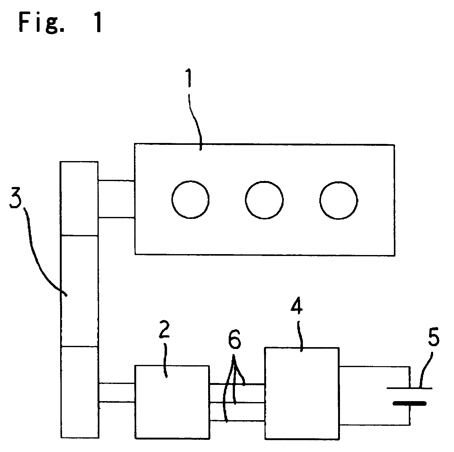
[0037]FIG. 1 is a system block diagram of a vehicle provided with an engine that is connected with an electric rotating machine via a belt.

[0038]Although FIG. 1 shows an example of connecting the electric rotating machine with the engine via the belt, the engine and the electric rotating machine may be connected with each other by any other method on condition that the electric rotating machine acts as both generator and a motor.

[0039]Referring now to the drawing, the electric rotating machine 2 is connected with the engine 1 via the belt 3. The electric rotating machine 2 is electrically connected to a control unit 4 with the use of three output harnesses 6. The control unit 4 is electrically connected to a battery 5.

[0040]The control unit 4 controls the electric rotating machine 2 to act as either motor or generator.

[0041]At the time of starting the engine 1, the control...

embodiment 2

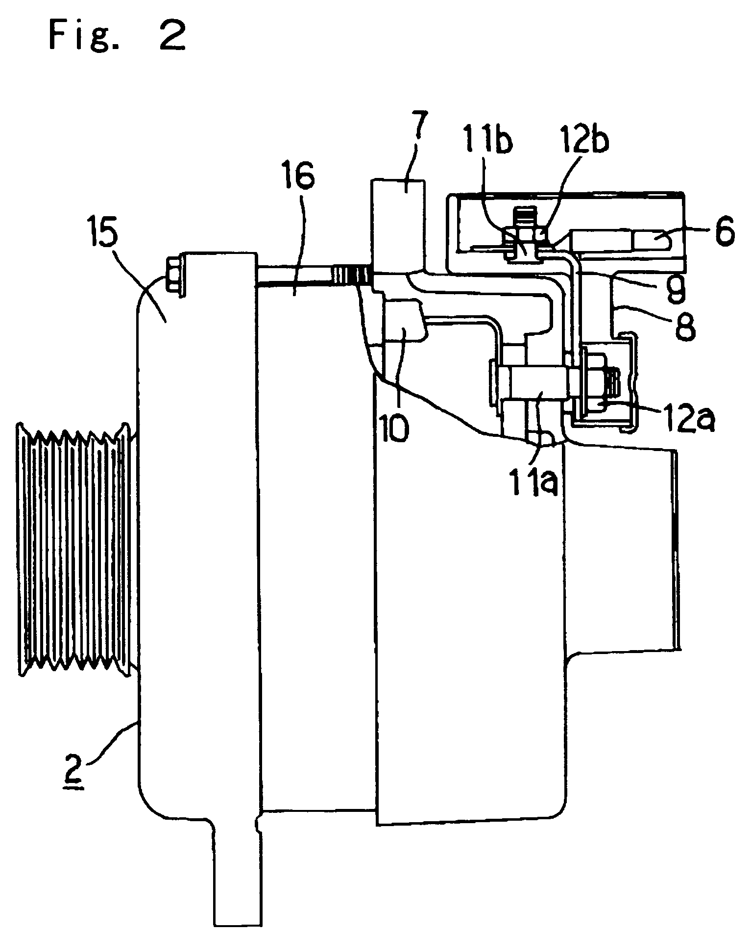
[0055]FIG. 6 is a partially side view showing an electric rotating machine according to Embodiment 2 of this invention, and FIG. 7 is a rear view taken in the direction A.

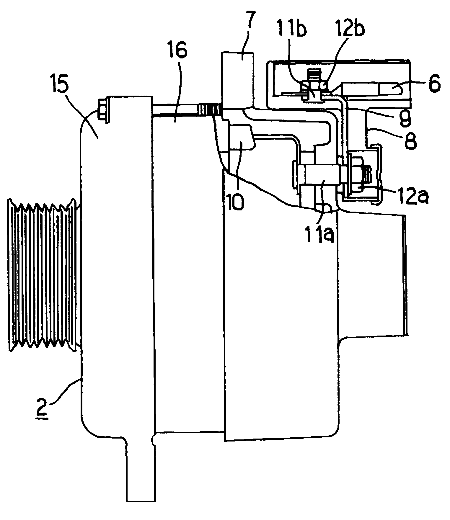
[0056]Referring to the drawings, the output terminal board 8 is disposed on a rear end face 2a of the rear bracket 7 of the electric rotating machine 2. The output harnesses 6 are arranged to extend in parallel to the rear end face 2a.

[0057]This embodiment is advantageous especially in the case that there is any obstacle in the rear of the electric rotating machine 2, i.e., behind the rear bracket 7 side and the output harnesses 6 are difficult to be disposed at the portion blocked by the obstacle.

[0058]FIG. 8 is a partially side view showing an electric rotating machine according to another example and FIG. 9 is a rear view taken in the direction A of FIG. 8. In the same manner as in FIGS. 6 and 7, the output terminal board 8 is disposed on the rear end face 2a of the rear bracket 7 of the electric rotating machi...

embodiment 3

[0062]FIG. 10 is a side view showing an electric rotating machine according to the embodiment 3 of this invention, and FIG. 11 is a rear view taken in the direction A of FIG. 10.

[0063]Referring to the drawings, the output terminal board 8 is disposed on a side face 7a of the rear bracket 7 of the electric rotating machine 2. The three output harnesses 6 are disposed in a direction tangential to a circumferential line 2b forming the outer periphery of the electric rotating machine 2 and are arranged to extend substantially in parallel to one another.

[0064]This embodiment is advantageous especially in the case that there is any obstacle in the rear of the electric rotating machine 2, i.e., behind the rear bracket 7 side and the output harnesses 6 are difficult to be disposed at the portion blocked by the obstacle.

[0065]As described above, according to this embodiment, since the output harnesses 6 are taken out in the circumferential direction of the bracket 7, the wiring layout can oc...


PUM


Abstract

An output terminal board of this invention is capable of improving easy and simple installation of an electric rotating machine and wiring output harnesses so as to avoid thermal influence from a stator. The electric rotating machine 2 for vehicle acting as a moter or a generator includes brackets 7 and 15 on both front side (pulley side) and rear side of a stator. Further, the electric rotating machine 2 includes a stator three-phase output line output portion and is provided with an output terminal board 8 at one bracket 7, the output terminal board 8 having a terminal for connecting the three-phase output harnesses 6 connected to an external controller. This output terminal board 8 is disposed in such a manner as being capable of joining to the bracket 7 side on which the output terminal board 8 is mounted, and the three output harnesses 6 are taken out substantially in parallel to one another.

Description

BACKGROUND OF THE INVENTION[0001]1. Field of the Invention[0002]This invention relates to an electric rotating machine for vehicle and, more particularly, to an output terminal structure for connection of three-phase output harness and a stationary structure of the terminal structure.[0003]2. Description of the Related Art[0004]In the conventional output terminal board structure of an electric rotating machines for vehicle, an output terminal extends in axial direction of the electric rotating machine, or is formed in radial direction of the electric rotating machine (as disclosed in, for example, the Japanese Patent Publication No.2585896, the Japanese Utility Model Registration Publication No.2505086).[0005]Since the conventional output terminal structure of the electric rotating machines for vehicle is constructed as mentioned above, it may be said that the output terminal extends efficiently from axial direction of the electric rotating machine to radial direction thereof. In th...

Claims


Application Information

Patent Timeline
IPC IPC(8): H01R9/22H01R4/30H02G3/30H02K5/22
CPCH02K5/225H01R4/30H02K5/22
Inventor MORIKAKU, HIDEKIASAO, YOSHIHITOKURIBAYASHI, MASARU
Owner MITSUBISHI ELECTRIC CORP
Why Eureka
Try Eureka