
Monitoring an optical element of a processing head of a thermal machine tool

Active Publication Date: 2006-04-04
TRUMPF LASER GMBH CO KG
View PDF11 Cites 5 Cited by
  • Summary
  • Abstract
  • Description
  • Claims
  • Application Information

AI Technical Summary

Benefits of technology

[0010]One or more of the following features may be included. The optical surface into which the light beam is coupled can face away from the workpiece. The detector can be disposed on one side of the optical element and the light source disposed on the other side of the optical element. The detector can be disposed in proximity with the optical surface on the side of the optical element opposite from the workpiece. The apparatus may further include a second detector for detecting a portion of the light beam scattered in the region of the optical s

Problems solved by technology

Consequently, the thermal load of the optical element is increased which produces in the end a noticeable reduction of the laser performance available in the processing region.
For heavy soiling, in particular through splashes, the increased absorption of laser radiation could destroy the optical element.
A decrease in intensity means increasing thermal load of the optical element.
However, the protecting glass may be destroyed before the temperature detector reacts due to the poor thermal conductivity of glass.

Method used


Image

  • Monitoring an optical element of a processing head of a thermal machine tool
  • Monitoring an optical element of a processing head of a thermal machine tool
  • Monitoring an optical element of a processing head of a thermal machine tool

Examples


Embodiment Construction

[0018]It is desirable to further improve detection of soiling of the optical element of the processing head of a machine for thermal processing of a workpiece.

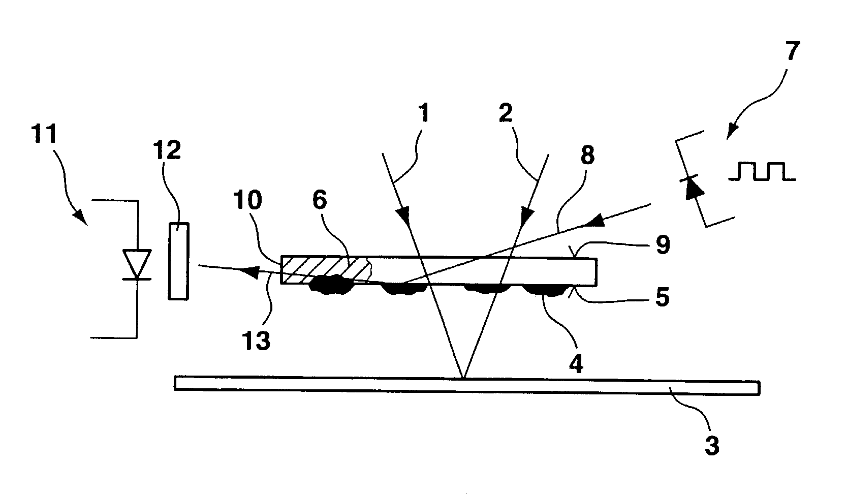
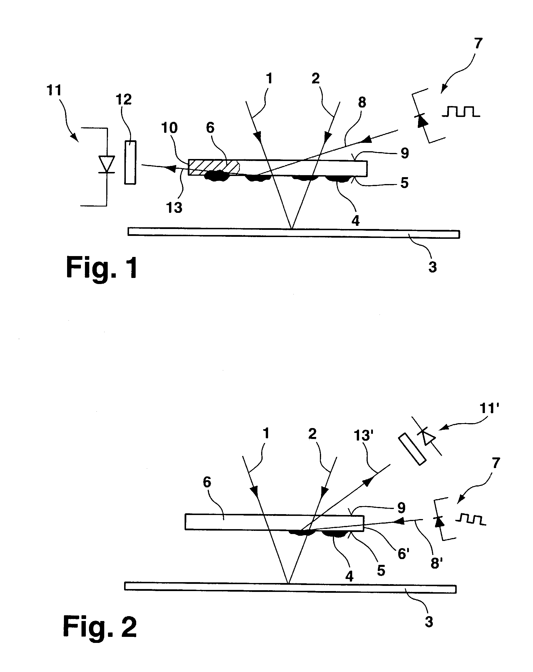
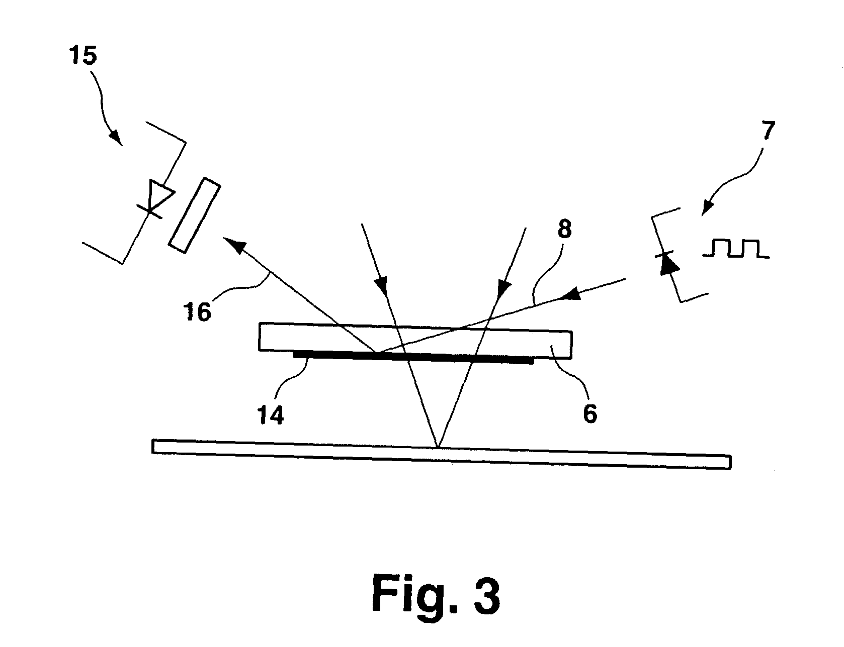
[0019]This objective may be achieved by using an apparatus to monitor an optical element of a processing head of a machine for thermal processing of a workpiece, in particular a laser processing machine, that includes a separate light source for coupling a light beam into the optical element on the optical surface facing away from a workpiece or on a lateral edge or on a lateral surface and a detector for detecting a light beam reflected or scattered in the region of the optical surface facing the workpiece. The relevant region of the workpiece includes the optical surface itself, the volume or material interior behind the surface and also particles deposited or burnt into this region. Soiling of the optical surface facing a workpiece can be detected and displayed independently of the process parameters. The optical element ca...


PUM

PropertyMeasurementUnit
Lightaaaaaaaaaa
Optical propertiesaaaaaaaaaa
Proximity effectaaaaaaaaaa

Abstract

An apparatus for monitoring an optical element of a processing head of a machine for thermal processing of a workpiece includes a light source for coupling a light beam into an optical surface of an optical element and a detector for detecting a portion of the light beam scattered in the region of the optical surface facing the workpiece.

Description

CLAIM OF PRIORITY[0001]This application claims priority under 35 USC § 119(a) to European Patent application number 02008885.2-1262, filed Apr. 20, 2002, the entire contents of which are hereby incorporated by reference.TECHNICAL FIELD[0002]This invention relates to optical monitoring devices, and more particularly to devices for monitoring an optical element of a processing head of a thermal machine tool.BACKGROUND[0003]For processing workpieces by a machine for thermal welding or cutting, in particular a laser processing machine, splashes and smoke are produced in the processing region of the workpiece. The splashes and smoke can deposit on an optical surface, facing the workpiece, of an optical element of the processing head of the machine and soil the optical element. Splashes can burn into the optical surface. Smoke is deposited on the optical surface and can be removed from the optical surface to a certain degree. Deposits or damage to the optical surface produce increased abs...

Claims


Application Information

Patent Timeline
IPC IPC(8): G01N21/88B23K26/42G01N21/15G01N21/55
CPCB23K26/422G01N21/15G01N2021/157G01N21/55B23K26/702B23K26/707
Inventor HUTT, JOCHENFLAIG, RAINER
Owner TRUMPF LASER GMBH CO KG
Features
  • Generate Ideas
  • Intellectual Property
  • Life Sciences
  • Materials
  • Tech Scout
  • Unparalleled Data Quality
  • Higher Quality Content
  • 60% Fewer Hallucinations
Learn More