MRI-guided temperature mapping of tissue undergoing thermal treatment

a thermal treatment and temperature mapping technology, applied in the direction of nmr measurement, therapy, instruments, etc., can solve the problems of limited time for acquiring temporal mr images for monitoring temperature, inability to measure absolute prf, and limited spa

Inactive Publication Date: 2003-02-18
INSIGHTEC
View PDF4 Cites 170 Cited by
  • Summary
  • Abstract
  • Description
  • Claims
  • Application Information

AI Technical Summary

Problems solved by technology

Because of a non-homogenous magnetic field within the MRI machine, absolute PRF measurements are not possible.
Thus, there is limited time for acquiring temporal MR images for monitoring the temperature increase during a sonication in order to verify a sufficie...

Method used


Image

  • MRI-guided temperature mapping of tissue undergoing thermal treatment
  • MRI-guided temperature mapping of tissue undergoing thermal treatment
  • MRI-guided temperature mapping of tissue undergoing thermal treatment

Examples


Embodiment Construction

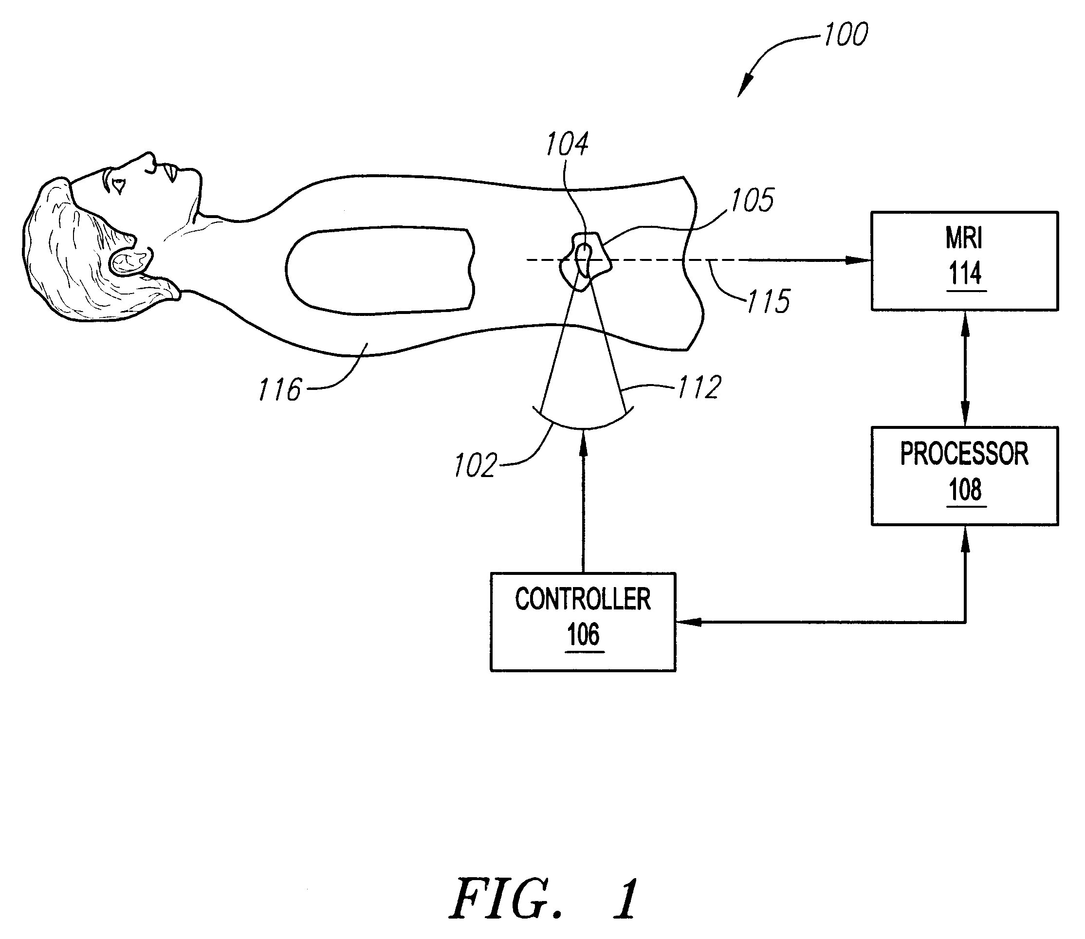
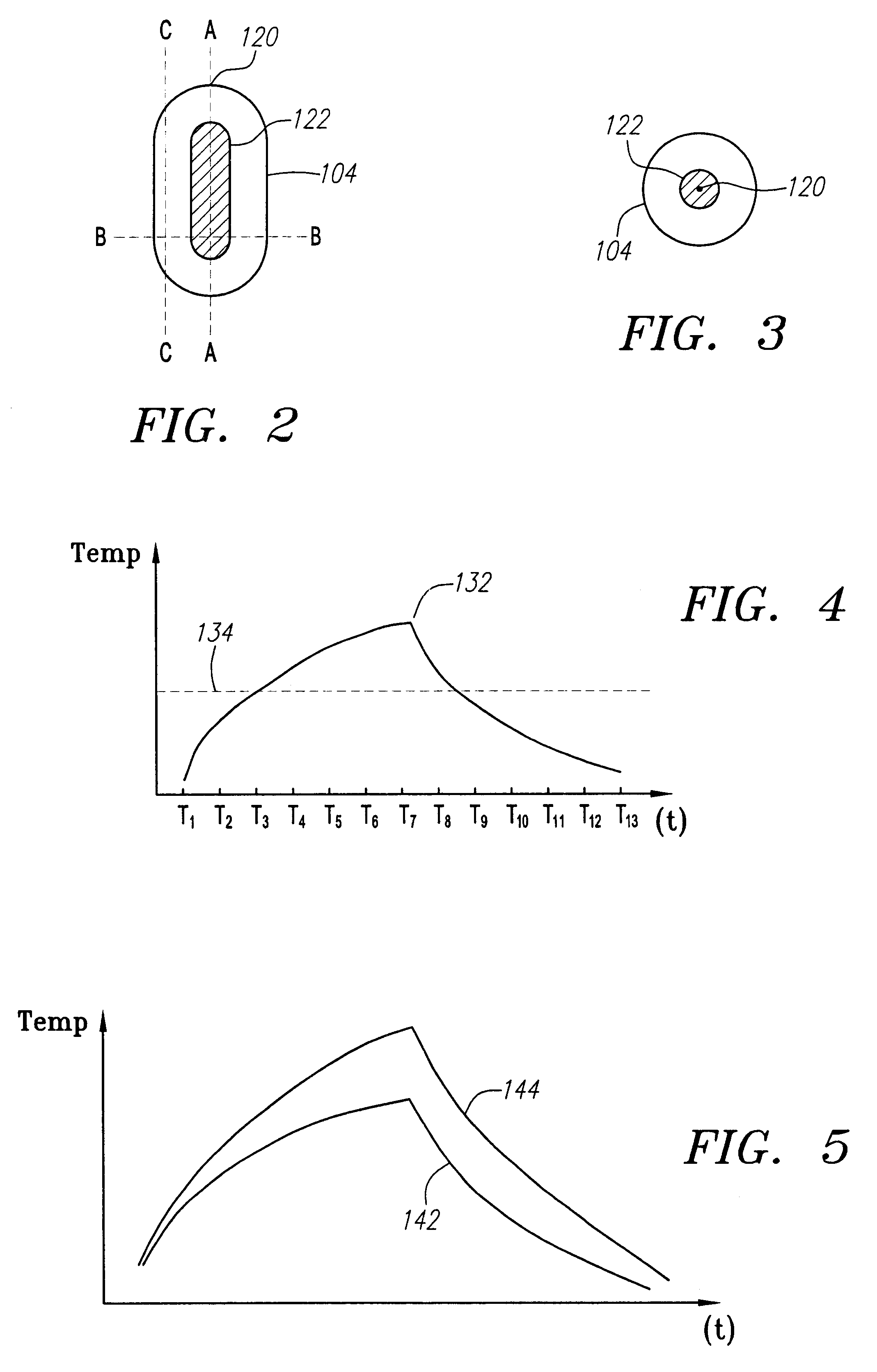
FIG. 1 is a simplified schematic illustration of an exemplary MRI-guided focussed ultrasound thermal treatment system 100. The system 100 includes a phased array transducer 102 driven by a controller 106 for emitting a beam of focussed ultrasound energy 112 converging in a focal zone 104 located in a target tissue mass 105 in a patient 116. The geometry of the focal zone 104 within the target tissue structure 105 is a function of the shape of the transducer 102 and phasing of the individual transducer elements, which dictate the interaction of the converging ultrasonic waves. In the illustrated embodiment, the transducer is a concave, spherical cap, such the focal zone 104 will have a generally elongate shape, symmetrical about a focal axis, as shown in FIGS. 2 and 3.

Thermal conduction in the tissue mass 105 and cooling blood flow may also play a role in the actual thermal energy distribution in the tissue mass 105. Also, for a given output power of the energy beam 112 and volume of...


PUM


Abstract

Systems and methods using magnetic resonance imaging for monitoring the temperature of a tissue mass being heated by energy converging in a focal zone that is generally elongate and symmetrical about a focal axis. A first plurality of images of the tissue mass are acquired in a first image plane aligned substantially perpendicular to the focal axis. A cross-section of the focal zone in the first image plane is then defined from the first plurality of images. A second plurality of images are acquired of the tissue mass in a second image plane aligned substantially parallel to the focal axis, the second image plane bisecting the first image plane at approximately a midpoint of the defined focal zone cross-section.

Description

1. Field of the InventionThe present invention relates generally to magnetic resonance imaging (MRI) guided thermal treatment systems, and more particularly to using MRI to obtain thermal evolution images of a tissue mass undergoing thermal treatment.2. Background of the InventionCertain types of body tissues, such as tumors, can be destroyed by heat. One way to apply thermal energy to internal body tissue is to focus high intensity, ultrasonic acoustic waves into the tissue using, e.g., a phased-array of piezoelectric transducers. Such treatment can reduce or even eliminate the need for invasive surgery to remove the tissue. Of critical importance to the treatment process is verifying that a sufficient thermal dose is reached during each application of ultrasonic energy (or "sonication") to kill / ablate the portion of the target tissue structure being heated. It is also important to be able to precisely track which portions of the tissue structure have been killed / ablated, in order ...

Claims


Application Information

Patent Timeline
IPC IPC(8): A61B5/00A61B5/055G01R33/48G01R33/28A61B17/00A61B18/00A61B19/00A61F7/00A61N7/02
CPCA61B5/01A61B5/055G01R33/4804A61N7/02A61B2019/5236A61B2017/00084A61B2090/374
Inventor FREUNDLICH, DAVID
Owner INSIGHTEC
Why Eureka
Try Eureka