Navigational control system for a robotic device

a robotic device and control system technology, applied in the field of mobile robotic devices, can solve the problems of inability to use global positioning methods, inability to use deterministic cleaning robotic devices, and high cost of robotic devices, so as to improve the cleaning efficiency of robotic devices

Active Publication Date: 2006-04-04
IROBOT CORP
View PDF19 Cites 432 Cited by
  • Summary
  • Abstract
  • Description
  • Claims
  • Application Information

AI Technical Summary

Benefits of technology

[0014]One object of the present invention is to provide a navigational control system that enhances the cleaning efficiency of a robotic device by adding a deterministic component (in the form of a conduct prescribed by a navigation control algorithm) to the random motion of the robotic device generated by predetermined behavioral modes stored in the robotic device.

Problems solved by technology

A suitable positioning system—a positioning system suitably accurate for deterministic cleaning might rely on scanning laser ranging systems, ultrasonic transducers, a carrier phase differential GPS, or other sophisticated methods—is typically prohibitively expensive and labor intensive, requiring an involved pre-setup to accommodate the unique conditions of each area to be cleaned, e.g., room geometry, furniture locations.
In addition, methods that rely on global positioning are typically incapacitated by failure of any part of the positioning system.
One illustrative example of a highly sophisticated (and relatively expensive) robotic device for deterministic cleaning is the RoboScrub device built by Denning Mobile Robotics and Windsor Industries.
This target accessibility requirement effectively limits the use of the RoboScrub device to large uncluttered open areas.
These representative deterministic robotic devices are likewise relatively expensive, require labor intensive pre-setup, and / or are effectively limited to large, uncluttered areas of simple geometric configuration (square, rectangular rooms with minimal (or no) furniture).
Due to the limitations and difficulties inherent in purely deterministic cleaning systems, some robotic devices rely on pseudo-deterministic cleaning schemes such as dead reckoning.
In addition to the disadvantages of having to start cleaning operations from a fixed position with the robotic device in a specified orientation, the drive wheels of dead reckoning robotic devices are almost always subject to some degree of slippage, which leads to errors in the calculation of current position.
Accordingly, dead reckoning robotic devices are generally considered unreliable for cleaning operations of any great duration—resulting in intractable system neglect, i.e., areas of the surface to be cleaned are not cleaned.
Therefore, while a random motion robotic device is a relatively inexpensive means of cleaning a defined working area as contrasted to a deterministic robotic device, the random-motion robotic device requires a significantly higher cleaning time.

Method used


Image

  • Navigational control system for a robotic device
  • Navigational control system for a robotic device
  • Navigational control system for a robotic device

Examples


Embodiment Construction

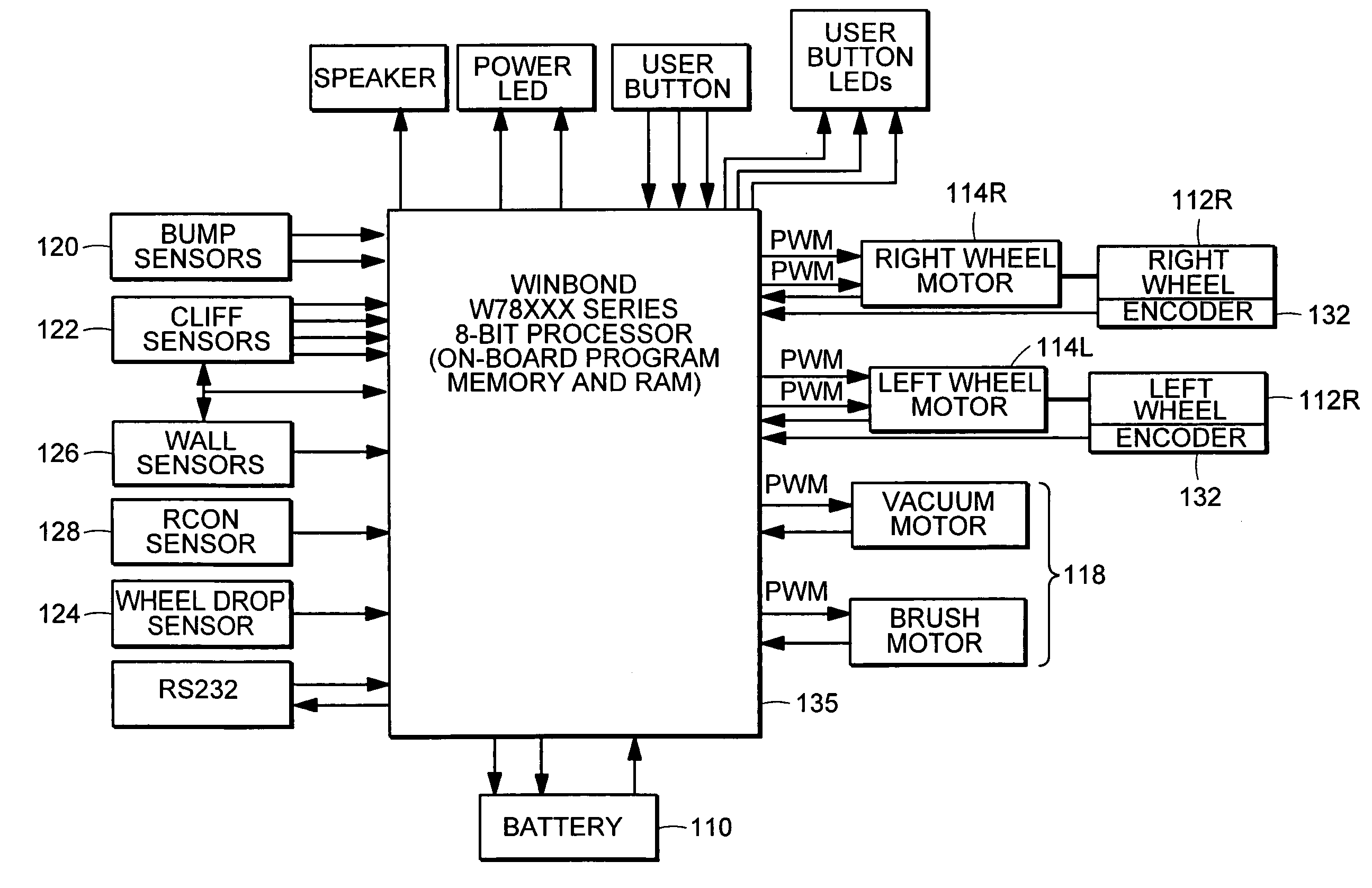
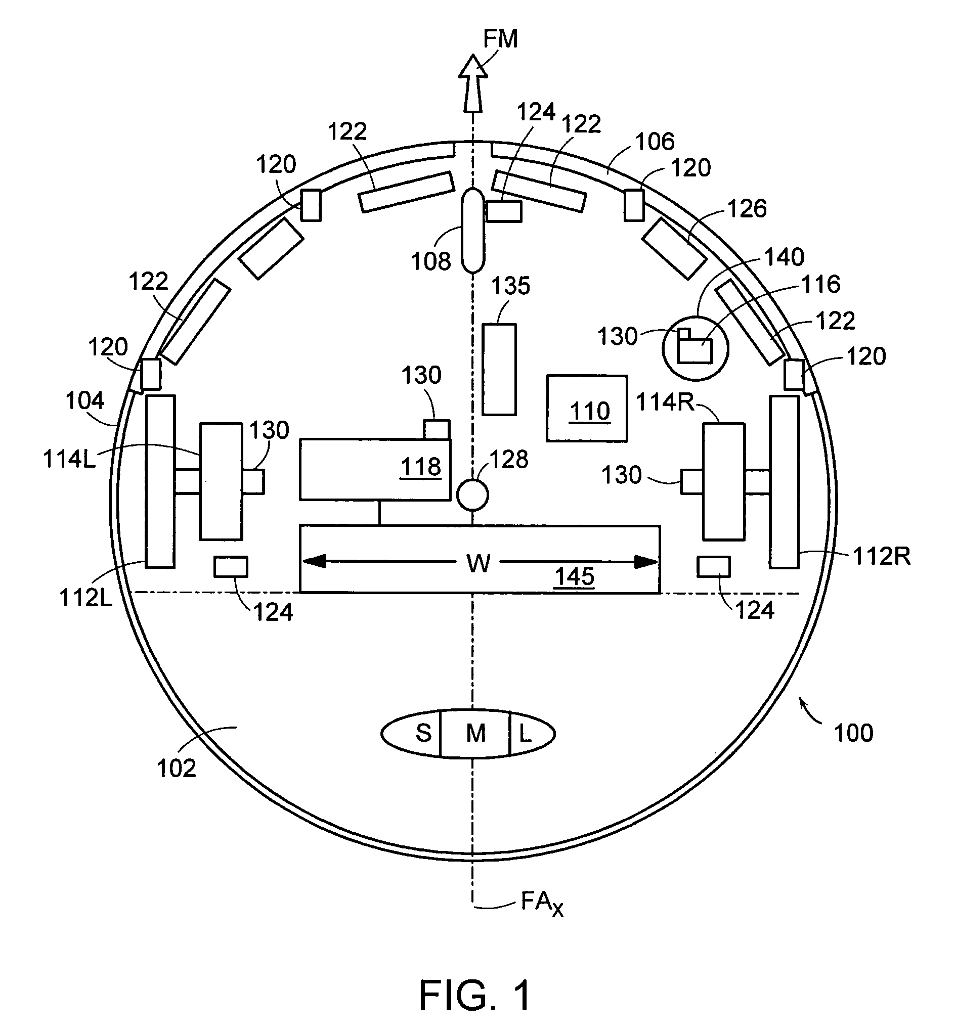
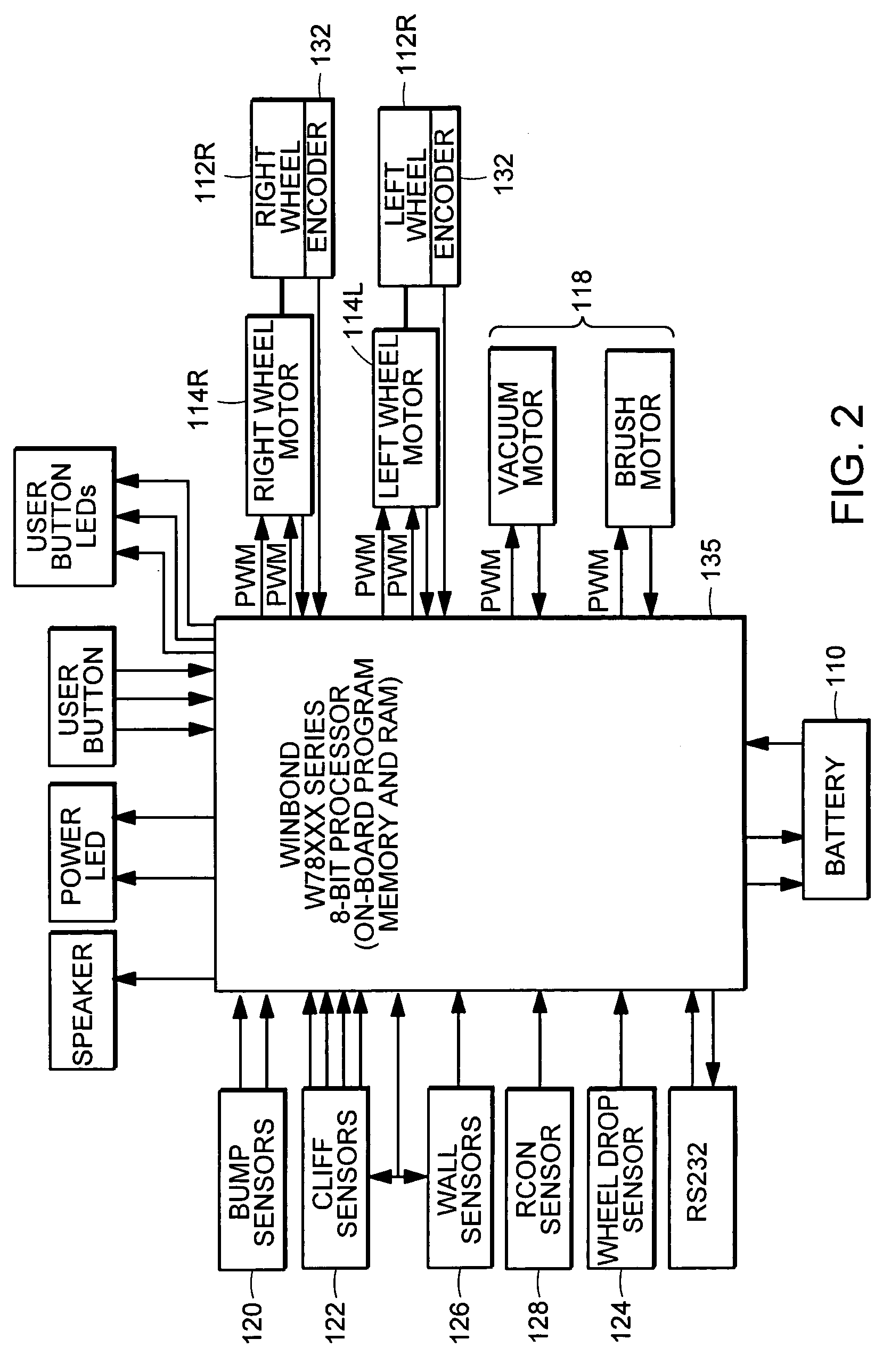
[0030]Referring now to the drawings wherein like reference numerals identify corresponding or similar elements throughout the several views, FIG. 1 is a top-view schematic of an exemplary preferred embodiment of a robotic device 100 having particular utility in combination with a navigational control system 10 according to the present invention. FIG. 2 is a block diagram of the hardware of the robot device 100 of FIG. 1.

[0031]The hardware and behavioral modes (coverage behaviors for cleaning operations; escape behaviors for transitory movement patterns; and safety behaviors for emergency conditions) of the robotic device 100, which is manufactured, distributed, and / or marketed by the iRobot Corporation of Burlington, Mass. under the ROOMBA trademark, are briefly described in the following paragraphs to facilitate a more complete understanding of the navigational control system 10 of the present invention. Further details regarding the hardware and behavioral modes of the robotic dev...


PUM


Abstract

A navigational control system for altering movement activity of a robotic device operating in a defined working area, comprising a transmitting subsystem integrated in combination with the robotic device, for emitting a number of directed beams, each directed beam having a predetermined emission pattern, and a receiving subsystem functioning as a base station that includes a navigation control algorithm that defines a predetermined triggering event for the navigational control system and a set of detection units positioned within the defined working area in a known spaced-apart relationship, the set of detection units being configured and operative to detect one or more of the directed beams emitted by the transmitting system; and wherein the receiving subsystem is configured and operative to process the one or more detected directed beams under the control of the navigational control algorithm to determine whether the predetermined triggering event has occurred, and, if the predetermined triggering event has occurred transmit a control signal to the robotic device, wherein reception of the control signal by the robotic device causes the robotic device to implement a prescribed conduct that alters the movement activity of the robotic device.

Description

CROSS-REFERENCE TO RELATED APPLICATION[0001]This nonprovisional patent application is based upon and claims priority from U.S. provisional patent application Ser. No. 60 / 410,480, filed 13 Sep. 2002, entitled BEACON-BASED NAVIGATIONAL SYSTEM.[0002]This nonprovisional patent application is related to commonly-owned, co-pending U.S. nonprovisional patent application Ser. No. 10 / 056,804, filed 24 Jan. 2002, entitled METHOD AND SYSTEM FOR ROBOT LOCALIZATION AND CONFINEMENT, U.S. nonprovisional patent application Ser. No. 10 / 320,729, filed 16 Dec. 2002, entitled AUTONOMOUS FLOOR-CLEANING DEVICE, U.S. nonprovisional patent application Ser. No. 10 / 167,851, filed 12 Jun. 2002, entitled METHOD AND SYSTEM FOR MULTI-MODE COVERAGE FOR AN AUTONOMOUS ROBOT, and U.S. nonprovisional continuation-in-part patent application Ser. No. 10 / 453,202, filed 03 Jun. 2003, entitled ROBOT OBSTACLE DETECTION SYSTEM, each of which is hereby incorporated by reference.BACKGROUND OF THE INVENTION[0003](1) Field of t...

Claims


Application Information

Patent Timeline
Patent Type & Authority Patents(United States)
IPC IPC(8): G06F19/00G01B11/03G05D1/02
CPCG05D1/0242G05D1/0272G05D1/0225G05D2201/0203G05D1/0274G01S5/16G01S5/12
Inventor CHIAPPETTA, MARK J.JONES, JOSEPH L.
Owner IROBOT CORP
Why Eureka
Try Eureka