
Method for generating rocket motor data profiles for firings at various temperatures

a rocket motor and data profile technology, applied in the field of generating rocket motor burnback data, pressure versus time, thrust versus time data for various firing temperatures, can solve the problems of expensive, impractical and general availability of actual firing test data, and achieve the effect of avoiding the need for a series of test firings

Inactive Publication Date: 2006-04-04
THE UNITED STATES OF AMERICA AS REPRESENTED BY THE SECRETARY OF THE NAVY
View PDF2 Cites 2 Cited by
  • Summary
  • Abstract
  • Description
  • Claims
  • Application Information

AI Technical Summary

Benefits of technology

[0008]It is an object of the present invention to provide a method and implementation by computer model, which can mathematically develop an accurate curve for a temperature different from those temperatures for which firing test data is available.
[0026]The foregoing method eliminates the need for knowing the actual geometry of the propellant-grain and makes use of test firing data, such as, pressure and thrust data versus time, and measured throat area, along with general propellant grain and motor design data, such as propellant weight and density, web thickness, propellant pressure coefficient, thermal expansion coefficient, and temperature sensitivity coefficient to develop a burnback profile. Additionally, the method uses the user input information together with the profiles it has generated to build data profiles for temperatures, for which no test firing data is available. The type of input data required is that which is readily available to personnel involved in the analysis on a given rocket motor.

Problems solved by technology

Test data from actual firings can be used to plot the curve and produce a burnback profile but rocket motors are normally tested at extreme temperatures only and actual firing test data is generally not available for temperatures within the normal range of use, for the rocket motor.
It would be expensive and impractical to conduct a series of test firings, for each rocket motor, in order to obtain representative data for a spectrum of temperatures, so that curves could be generated from the data, for representative firing temperatures.

Method used


Image

  • Method for generating rocket motor data profiles for firings at various temperatures
  • Method for generating rocket motor data profiles for firings at various temperatures
  • Method for generating rocket motor data profiles for firings at various temperatures

Examples


Embodiment Construction

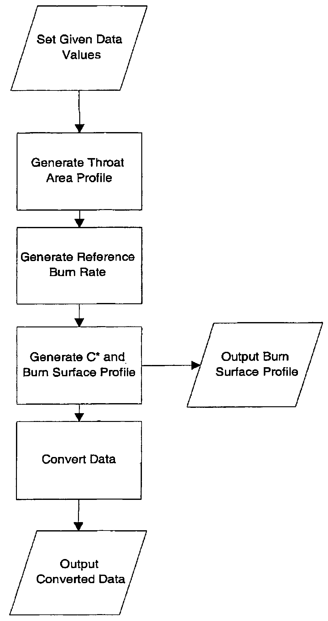
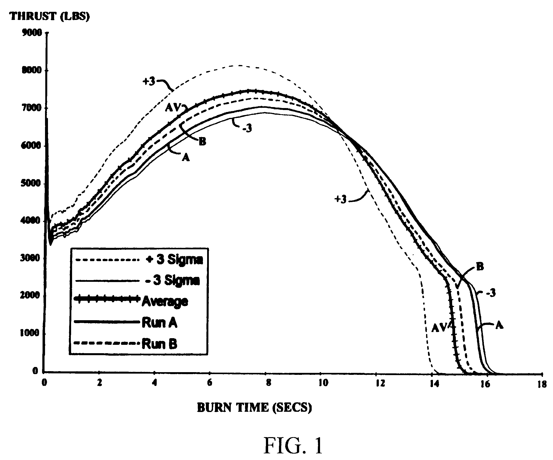
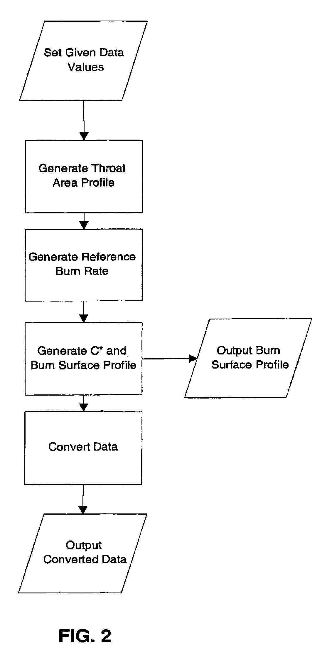
[0041]The present invention is a method for using a computer model for generating rocket motor profiles as in FIG. 1, inclusive of throat area profiles and thrust coefficient profiles, all from readily available rocket motor specification data and test firing data. The present method facilitates the generation of burnback profiles and pressure and thrust versus time data at firing temperatures for which no test firing data is available. This data is valuable for predicting the ballistics performance of particular rocket motors at various temperatures.

[0042]Typically a user who is engaged in analysis of rocket motors has access to specifications including web thickness, propellant weight, propellant density, initial throat diameter, thermal expansion coefficient, temperature sensitivity coefficient and pressure exponent. The user also has access to the data from one or more test firings, usually at extreme temperatures. This data comprises values for thrust at time increments and cha...


PUM


Abstract

A method for generating predictions of rocket motor ballistic performance at specific firing temperatures and for generating data profiles for analysis. The method requires generally available specifications for the rocket motor to be tested and test data from one or more test firings at a known temperature. The method is implemented in software form and generates pressure and thrust versus time data at a selected temperature. The method generates a burnback profile with a correct final web that integrates to the correct final propellant weight as well as a throat area profile and thrust coefficient profile, for the test firing temperature and for the temperature to be predicted.

Description

STATEMENT OF GOVERNMENT INTEREST[0001]The invention described herein may be manufactured and used by or for the Government of the United States of America for governmental purposes without payment of any royalties thereon or therefor.BACKGROUND[0002]a. Field of Invention[0003]The present invention relates to generating rocket motor burnback data, pressure versus time, and thrust versus time data for various firing temperatures, using generally available specifications of the rocket motor and test firing data.[0004]b. Background[0005]In order to simulate the ballistics performance of a particular rocket motor, it is necessary to have a burnback profile. A burnback profile is developed by plotting the burn surface area as a function of the linear web burned. FIGS. 7, 9, 11 and 13 are examples of burnback profiles. The area under the curve equals the volume of propellant burned. The curve is unique for each different rocket motor and is a function of the geometry of the propellant grai...

Claims


Application Information

Patent Timeline
Patent Type & Authority Patents(United States)
IPC IPC(8): G05D1/00F41G7/00F42B10/00G05D3/00
CPCF02K9/26F05D2260/80F05D2270/44
Inventor KING, JOHN M.
Owner THE UNITED STATES OF AMERICA AS REPRESENTED BY THE SECRETARY OF THE NAVY
Learn More