
System and method for analyzing noise

a technology of noise analysis and noise, applied in the field of noise analysis system, can solve the problems of crosstalk noise, waveform of signal transmitted from such a transistor is subject to the influence of crosstalk noise, and noise of crosstalk

Inactive Publication Date: 2006-04-04
KK TOSHIBA
View PDF7 Cites 10 Cited by
  • Summary
  • Abstract
  • Description
  • Claims
  • Application Information

AI Technical Summary

Benefits of technology

The present invention is a system and method for analyzing noise and determining if it will cause a malfunction in a receiver cell. The system includes an error information storage unit that stores threshold values for malfunction factors that create a malfunction in a receiver cell due to noise. An error criterion generation section selects the threshold values and generates an error criterion based on the receiver cell by plotting the threshold values and conducting them smooth processing. A noise analysis section measures the malfunction factors and compares them to the error criterion to determine if the noise will cause a malfunction in the receiver cell. This invention helps to improve the accuracy and reliability of analyzing noise and preventing malfunctions in receiver cells.

Problems solved by technology

In an integrated circuit, since a transistor with low output impedance has a large driving capability, the waveform of a signal transmitted from such a transistor tends to generate significant crosstalk noise in a signal propagated through an adjacent wire.
On the contrary, since a transistor with high output impedance has a low driving capability, the waveform of a signal transmitted from such a transistor is subject to the influence of crosstalk noise.
With increased integrated circuit density, the crosstalk noise, which causes a malfunction of a logic circuit, has been a significant problem.
However, the conventional crosstalk noise analysis method does not take into consideration the influence of crosstalk noise in a state where a rising or falling signal is being propagated (hereinafter, referred to as “a transition state”).
Therefore, the conventional crosstalk noise analysis method cannot completely prevent a malfunction of the receiver cell.
However, such design change leads to a large circuit design, thus increasing the circuit area and power dissipation and reducing speed of the circuit.

Method used


Image

  • System and method for analyzing noise
  • System and method for analyzing noise
  • System and method for analyzing noise

Examples


first embodiment

[0033](First Embodiment)

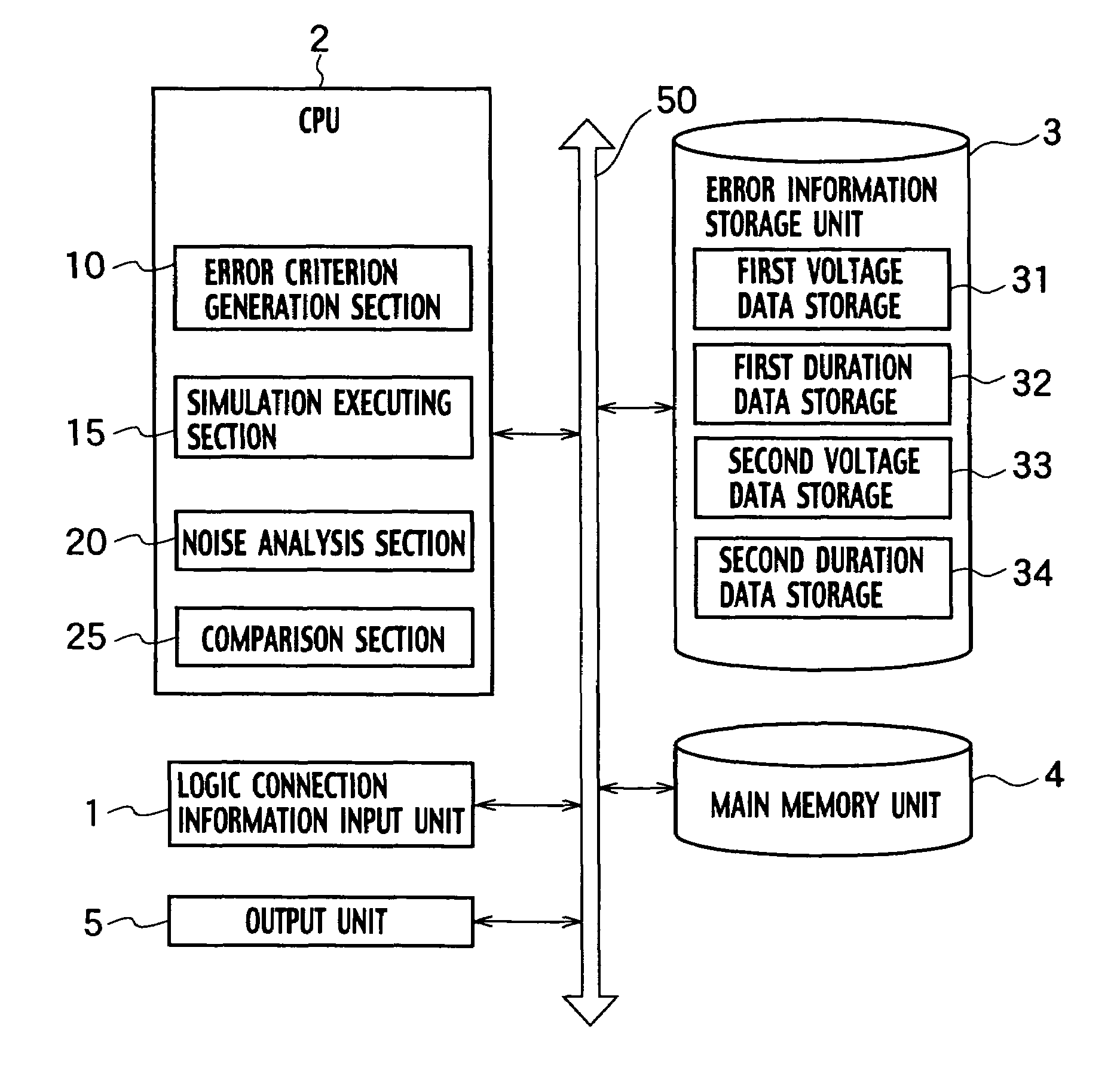
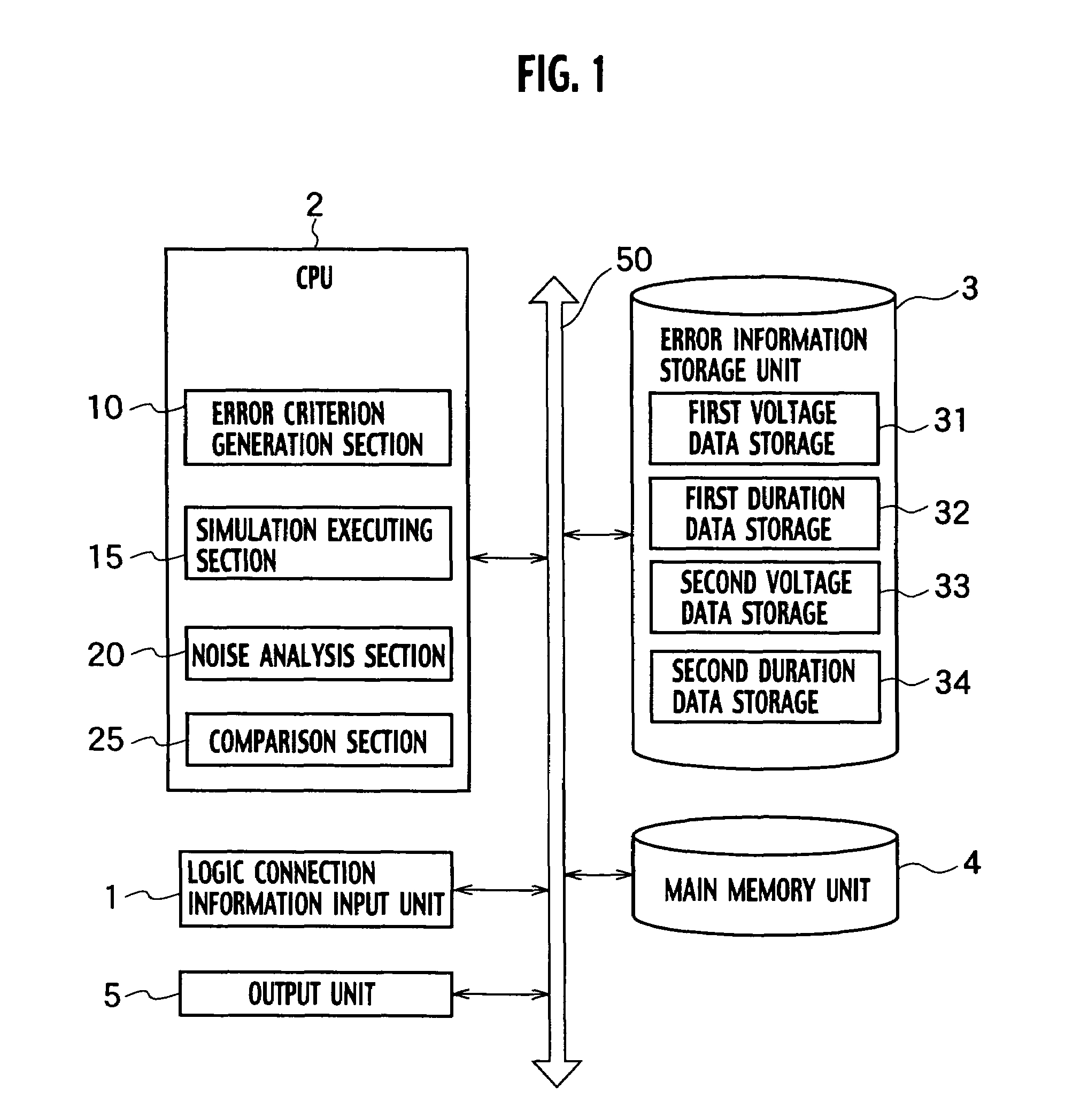
[0034]As shown in FIG. 1, a crosstalk noise analysis system according to a first embodiment of the present invention includes a logic connection information input unit 1, a CPU 2, an error information storage unit 3, a main memory unit 4, and an output unit 5, which are connected to a bus 50. The CPU 2 includes an error criterion generation section 10, a simulation executing section 15, a noise analysis section 20, and a comparison section 25.

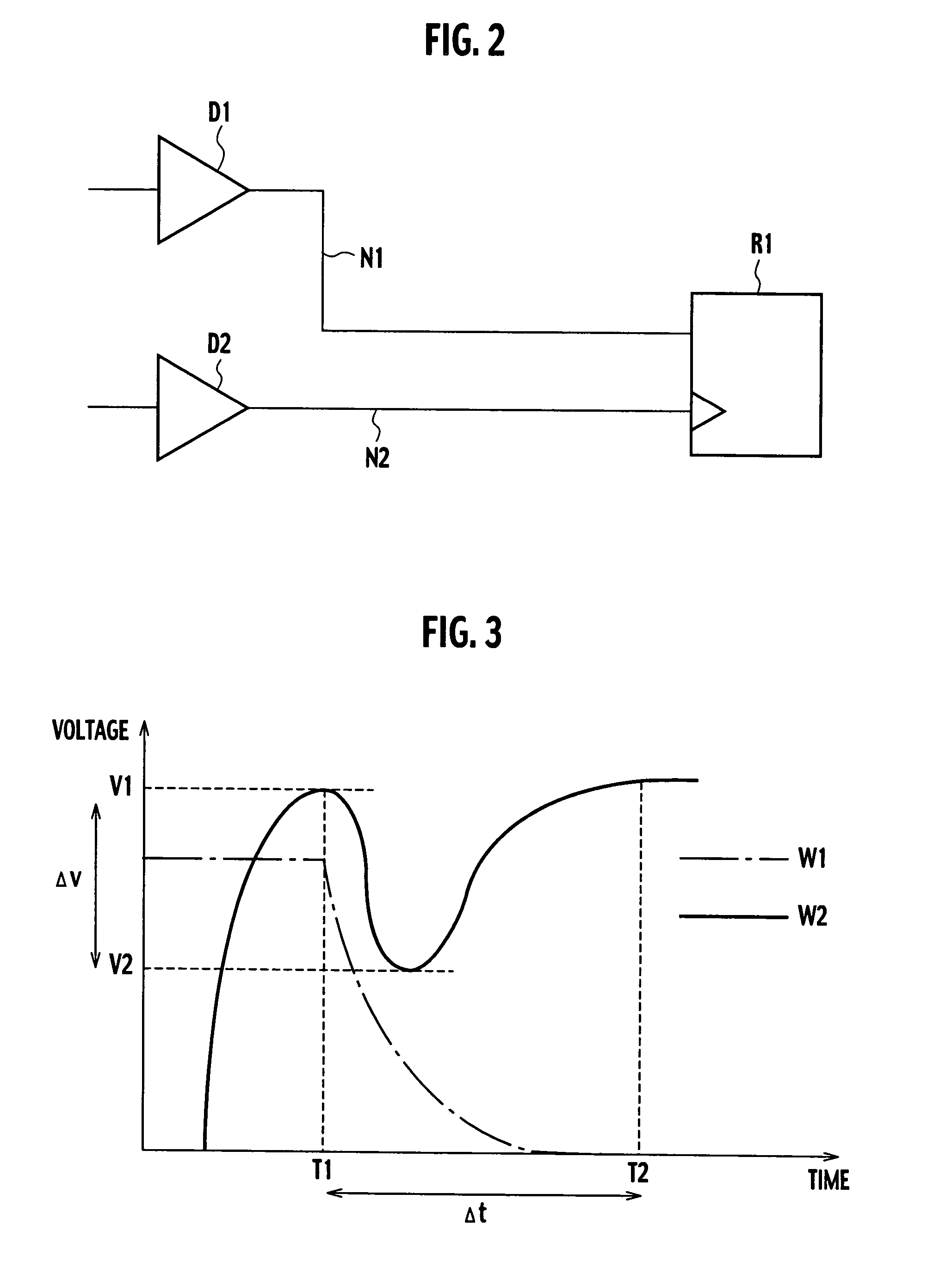
[0035]The logic connection information input unit 1 transmits data to the main memory 4 of a layout pattern of a logic circuit to be designed. For example, the logic connection information input unit 1 transmits data of a layout pattern of a logic circuit, which is composed of a receiver cell R1, a driver D2 which transmits a clock signal to the receiver cell R1 through a wire N2, a wire N1 adjacent to the wire N2, and a driver D1 which transmits a general signal through the wire N1 as shown in FIG. 2.

[0036]In this speci...

second embodiment

[0055](Second Embodiment)

[0056]As shown in FIG. 7, a crosstalk noise analysis system according to a second embodiment of the present invention differs from that according to the first embodiment of the present invention shown in FIG. 1 in that the error information storage unit 3 includes a data storage section 35 which stores victim receiver cell load capacity as error information.

[0057]The “victim receiver cell load capacity” indicates load capacity of the victim receiver cell when the victim receiver cell is malfunctioning because of crosstalk noise. For example, when the “the noise voltage in the falling signal (v)” and “the noise duration in the falling signal (t)” shown in FIG. 4 cause a malfunction of the receiver cell R1 in FIG. 2, the load capacity of the receiver cell R1 is stored in the data storage section 35 as the error information “victim receiver cell load capacity (C).”

[0058]In the case of selecting the noise voltage and duration in the falling signal, and the victi...

third embodiment

[0066](Third Embodiment)

[0067]As shown in FIG. 10, the crosstalk noise analysis system according to a third embodiment of the present invention differs from that according to the first embodiment of the present invention shown in FIG. 1 in that rising noise voltage in a constant signal is stored in a third voltage data storage 36, rising noise duration in a constant signal is stored in a third duration data storage 37, falling noise voltage in a constant signal is stored in a fourth voltage data storage 38, and falling noise duration in a constant signal is stored in a fourth duration data storage 39 as the error information, respectively. Moreover, the crosstalk noise analysis system according to the third embodiment of the present invention differs from that according to the first embodiment of the present invention shown in FIG. 1 in that it includes a net analysis section 6.

[0068]The “rising noise voltage in a constant signal” is voltage of crosstalk noise generated in a constan...


PUM


Abstract

A system and method for analyzing noise includes an error information storage unit storing threshold values of malfunction factors that create a malfunction of a victim receiver cell due to a noise, an error criterion generation section which selects the threshold values from the error information storage unit, and generates an error criterion according to the victim receiver cell by plotting the threshold values and conducting the threshold values smooth processing on, a noise analysis section configured to measure the malfunction factors, and a comparison section configured to compare the measured malfunction factors to the error criterion, and to judge whether the noise will create a malfunction of the victim receiver cell when the malfunction factors meet the error criterion.

Description

CROSS REFERENCE TO RELATED APPLICATIONS[0001]This application is based upon and claims the benefit of priority from the prior Japanese Patent Applications No. P2003-176643, filed on Jun. 20, 2003; the entire contents of which are incorporated herein by reference.BACKGROUND OF THE INVENTION[0002]1. Field of the Invention[0003]The present invention relates to technology for analyzing noise of an integrated circuit by use of a computer, and specifically relates to a noise analysis system and a noise analysis method to analyze crosstalk noise generated in wires of the integrated circuit.[0004]2. Description of the Related Art[0005]In an integrated circuit, since a transistor with low output impedance has a large driving capability, the waveform of a signal transmitted from such a transistor tends to generate significant crosstalk noise in a signal propagated through an adjacent wire. On the contrary, since a transistor with high output impedance has a low driving capability, the wavefor...

Claims


Application Information

Patent Timeline
Patent Type & Authority Patents(United States)
IPC IPC(8): G06F11/08G06F17/50H01L21/82H02H3/05
CPCG06F11/24
Inventor YODA, TOMOYUKI
Owner KK TOSHIBA
Learn More