Multiplier

Active Publication Date: 2006-04-04
TEXAS INSTR INC
View PDF5 Cites 16 Cited by
  • Summary
  • Abstract
  • Description
  • Claims
  • Application Information

AI Technical Summary

Problems solved by technology

Consequently, when power source Vcc=3 V, the Gilbert cell cannot operate with a high stability.
However, for the conventional low-voltage multipliers shown in FIGS. 9 and 10, there are t

Method used


Image

  • Multiplier
  • Multiplier
  • Multiplier

Examples


Embodiment Construction

[0065]In the following, an embodiment of this invention will be considered with reference to FIGS. 1–7.

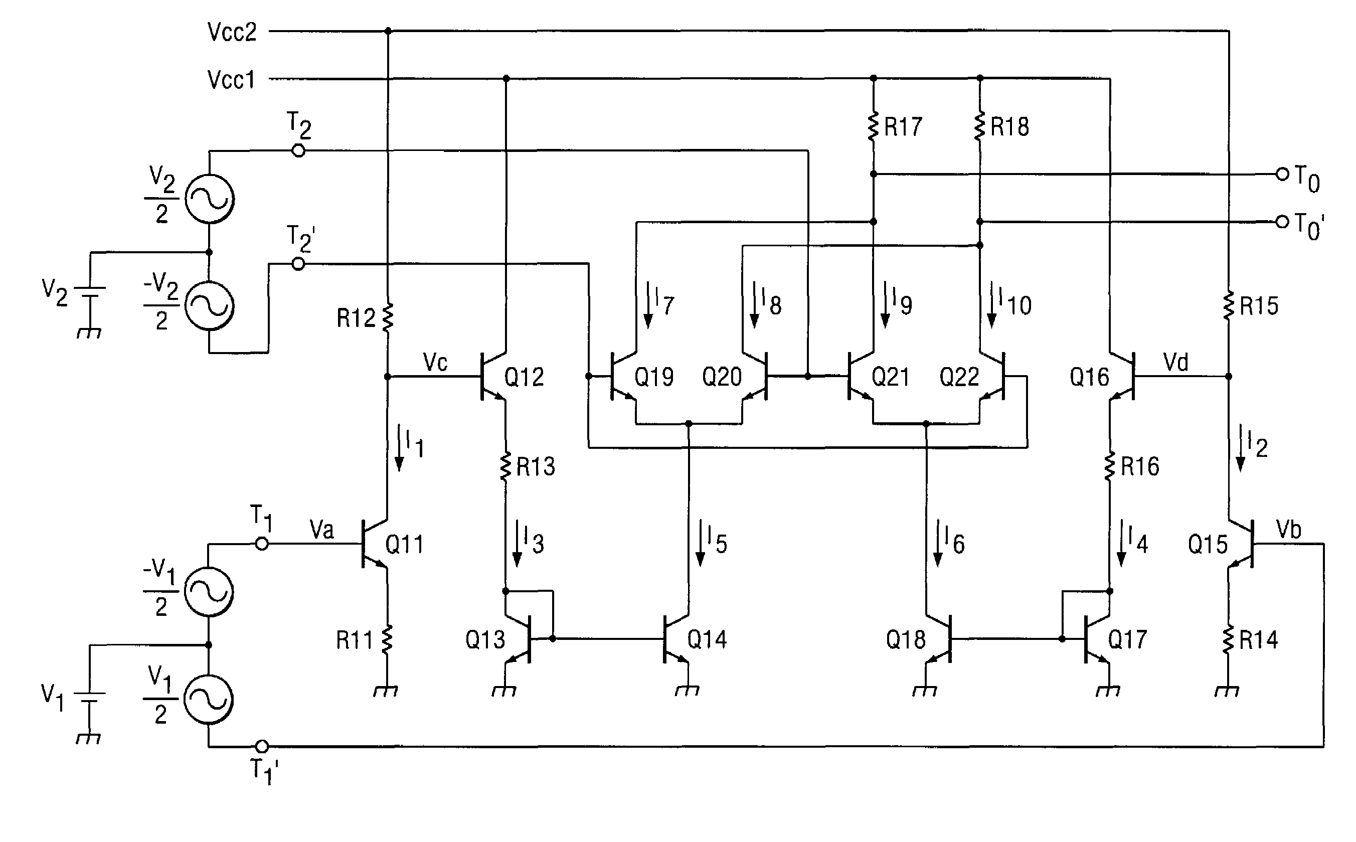
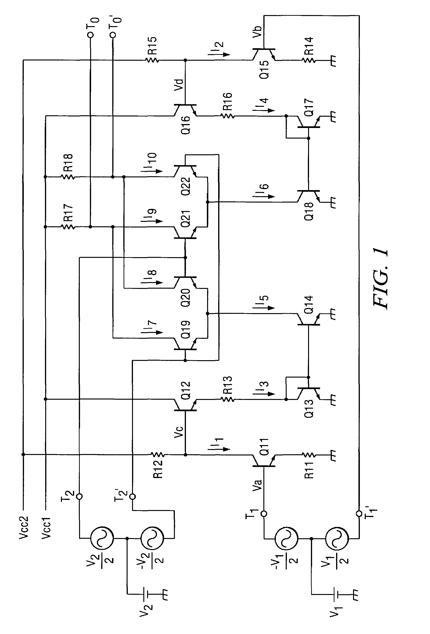
[0066]FIG. 1 is a schematic circuit diagram illustrating an example of a multiplier in an embodiment of this invention.

[0067]FIG. 1, Q11–Q22 represent npn transistors, R11–R18 represent resistors, and T1, T1′, T2, T2′, To and To′ represent terminals.

[0068]The emitters of npn transistor Q19 and npn transistor Q20 are both connected to the collector of npn transistor Q14. The emitters of npn transistors Q21 and Q22 are both connected to the collector of npn transistor Q18.

[0069]The bases of npn transistors Q20 and Q21 are both connected to terminal T2. The bases of npn transistors Q19 and Q22 are both connected to terminal T2′.

[0070]The collectors of npn transistors Q19 and Q21 are both connected to terminal To, and the connection node is connected through resistor R17 to power source Vcc1. The collectors of npn transistors Q20 and Q22 are both connected to terminal To′, and the conn...


PUM


Abstract

A multiplier having a simple constitution, excellent performance with respect to high-frequency characteristics and distortion characteristics, and allows low-voltage operation. Transistor Q11, resistors R11 and R12 form a common-emitter circuit. One signal of differential signal v1 is amplified by the common-emitter circuit, and the amplified signal is input to an emitter follower composed of transistor Q12. The output current of the emitter follower is input through resistor R13 into the current mirror circuit composed of transistors Q13 and Q14. Output current I5 of said current mirror circuit is input to the transistor pair of transistor Q19 and npn transistor Q20. By selecting an appropriate gain for the common-emitter circuit, currents I5 and I6 generated in this way become independent of the base-emitter voltage, and performance is improved with respect to distortion characteristics.

Description

FIELD OF THE INVENTION[0001]This invention pertains to a type of multiplier that performs multiplication to generate a signal as a product of two input signals.BACKGROUND OF THE INVENTION[0002]For example, the mixer circuit used in frequency converters and demodulators, etc. is often made of a circuit known as a Gilbert cell. The Gilbert cell is a circuit inverted by Mr. Barry Gilbert.[0003]FIG. 8 is a schematic circuit diagram illustrating the basic constitution of said Gilbert cell.[0004]In FIG. 8, Q1–Q6 represent npn transistors; CC1 represents a constant current circuit; R1 and R2 represent resistors; T1, T1′, T2, T2′, To and To′ represent terminals.[0005]The emitters of npn transistors Q1 and Q2 are connected to each other, and they are also connected to reference potential GND via constant current circuit CC1. The base of npn transistor Q1 is connected to terminal T1, and the base of npn transistor Q2 is connected to terminal T1′.[0006]The emitters of npn transistors Q3 and Q4...

Claims


Application Information

Patent Timeline
IPC IPC(8): G06G7/16G06G7/163H03F3/45
CPCG06G7/163
Inventor MATSUGAKI, YOSHIKATSUFUKUI, EIZO
Owner TEXAS INSTR INC
Why Eureka
Try Eureka