
Direct fuel injection/spark ignition engine control device

a technology of control device and spark ignition engine, which is applied in the direction of electric control, machines/engines, mechanical equipment, etc., can solve the problems of reduced air intake volume, difficult stable combustion, and low intake air density

Active Publication Date: 2006-04-11
NISSAN MOTOR CO LTD
View PDF11 Cites 12 Cited by
  • Summary
  • Abstract
  • Description
  • Claims
  • Application Information

AI Technical Summary

Benefits of technology

The present invention provides a control system for an engine that can optimally control combustion based on environmental conditions, especially when warming up the catalyst. The system includes an environment condition determination section, a catalyst condition determination section, and a combustion control section. The system can detect low air density or high outside temperature that may reduce the amount of air taken in, which can make it difficult to achieve stable combustion. The system can prevent this issue by performing a stratified combustion mode with compression stroke injection during startup when warming up the catalyst, and it can switch to an intake stroke injection mode when air density is low. This system helps to improve engine performance and operability in various environmental conditions.

Problems solved by technology

However, it has been discovered that the density of the intake air is low in high-altitude and other low-pressure environments and in environments where the outside air temperature is high.
Thus, in these situations, the actual quantity of air that can be taken in is reduced such that stable combustion is difficult.
In other words, in these situations, difficulties in starting occur due to the inability to generate the necessary engine torque when operation is performed by stratified combustion.
Even when the engine can be started, stable stratified combustion is also difficult to sustain during the engine warm-up period, and when the auxiliary load is increased after starting, for example, drawbacks in operability occur due to inadequate engine torque.

Method used


Image

  • Direct fuel injection/spark ignition engine control device
  • Direct fuel injection/spark ignition engine control device
  • Direct fuel injection/spark ignition engine control device

Examples


first embodiment

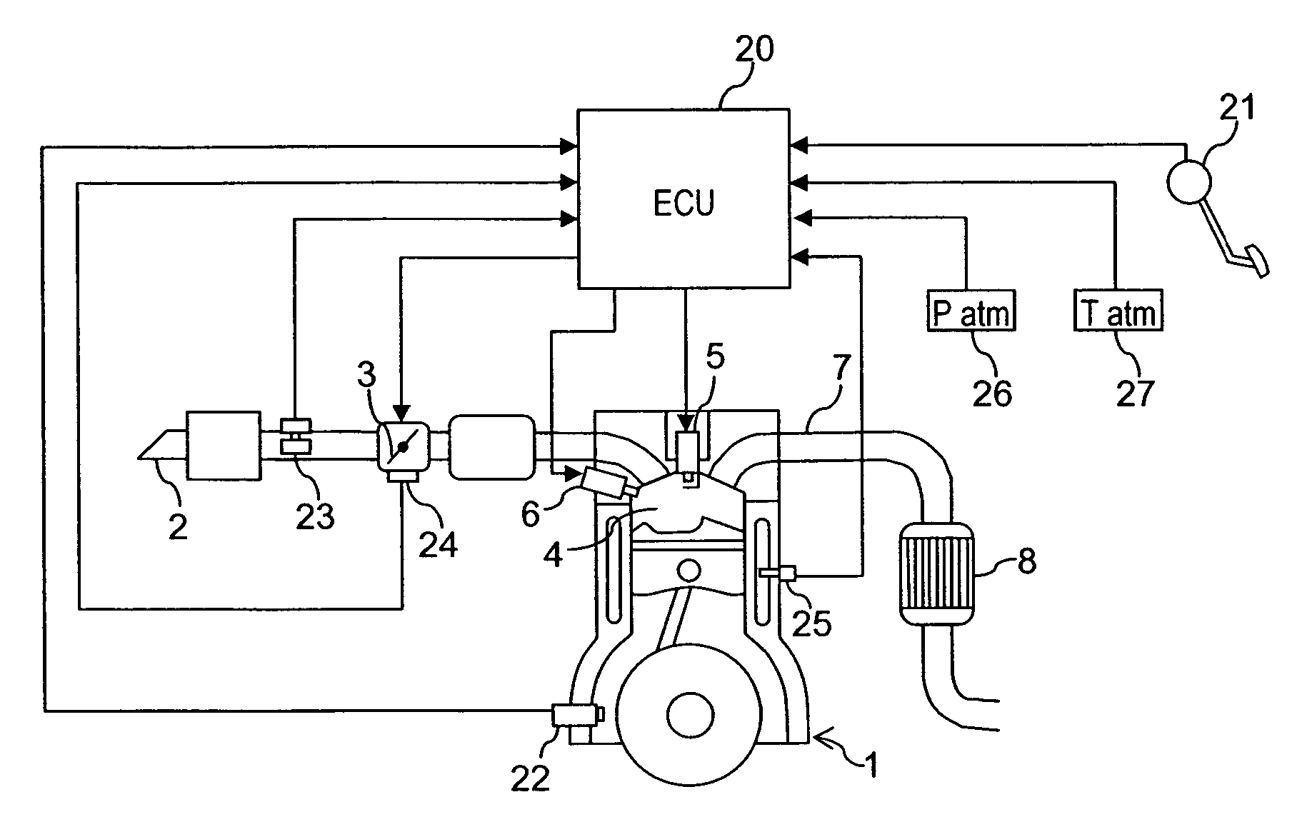
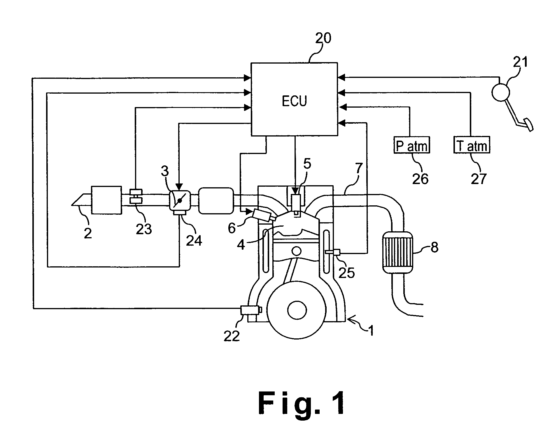
[0021]Referring initially to FIG. 1, a direct fuel injection / spark ignition engine 1 is diagrammatically illustrated that is equipped with a direct fuel injection / spark ignition engine control device in accordance with a first embodiment of the present invention. The engine 1 has an intake passage 2 with an electronically controlled throttle valve 3 mounted therein. The electronically controlled throttle valve 3 is configured and arranged for controlling the intake air quantity to the intake passage 2 of the engine 1. The intake passage 2 is fluidly connected to a plurality of combustion chambers 4 (only one shown) of the engine 1. Each combustion chamber 4 includes a spark plug 5 and a fuel injection valve 6. The spark plug 5 and the fuel injection valve 6 are mounted to the combustion chamber 4 in a conventional manner. The engine 1 also has an exhaust passage 7 fluidly connected to each combustion chamber 4. The exhaust passage 7 includes a catalytic converter 8 with a catalyst f...

second embodiment

[0049]Referring now to FIGS. 5 and 6, a direct fuel injection / spark ignition engine control device in accordance with a second embodiment of the present invention will next be described. The direct fuel injection / spark ignition engine control device of the second embodiment of the present invention is used in a vehicle equipped with the direct fuel injection / spark ignition engine 1 as seen in FIG. 1. In other words, the second embodiment is the same as the first embodiment, except for different programming of the engine control unit 20 is used in step S1. In view of the similarity between the first and second embodiments, the parts of the second embodiment that are identical to the parts of the first embodiment will be given the same reference numerals as the parts of the first embodiment. Moreover, the descriptions of the parts of the second embodiment that are identical to the parts of the first embodiment may be omitted for the sake of brevity. In other words, unless otherwise sp...

third embodiment

[0055]Referring now to FIGS. 5 and 6, a direct fuel injection / spark ignition engine control device in accordance with a third embodiment of the present invention will next be described. The direct fuel injection / spark ignition engine control device of the third embodiment of the present invention is used in a vehicle equipped with the direct fuel injection / spark ignition engine 1 as seen in FIG. 1. In other words, the third embodiment is the same as the first embodiment, except for different programming of the engine control unit 20 is used in step S1. In view of the similarity between the first and third embodiments, the parts of the third embodiment that are identical to the parts of the first embodiment will be given the same reference numerals as the parts of the first embodiment. Moreover, the descriptions of the parts of the third embodiment that are identical to the parts of the first embodiment may be omitted for the sake of brevity. In other words, unless otherwise specifie...


PUM


Abstract

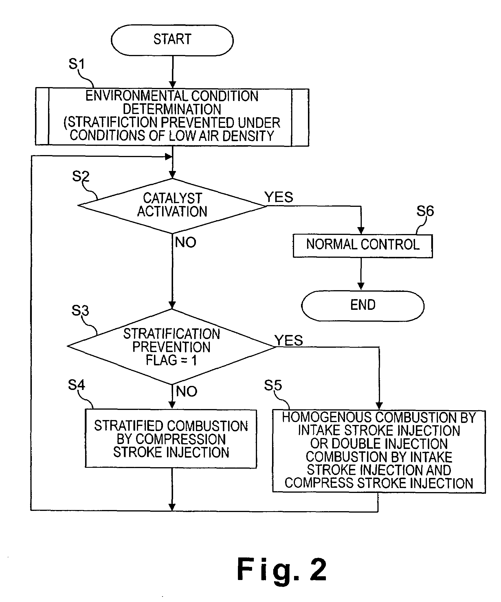
An engine control device is configured to perform optimum combustion control according to environmental conditions when warming up of a catalyst for emission purification is required. The engine control device performs stratified combustion by the compression stroke injection at the time of startup, when warming up of the catalyst is required. However, under conditions of low air density, stratified combustion by compression stroke injection is prevented, and either homogenous combustion by intake stroke injection is performed, or double injection combustion by intake stroke injection and compression stroke injection is performed. Thus, the engine control device maintains starting properties and prevents adverse effects on engine operability.

Description

BACKGROUND OF THE INVENTION[0001]1. Field of the Invention[0002]The present invention generally relates to a control device for a direct fuel injection spark ignition engine. More specifically, the present invention relates to a control device that is suitable during cold starting and the like, or when it is necessary to warm up a catalyst for exhaust purification provided to the exhaust channel.[0003]2. Background Information[0004]One example of a direct fuel injection spark ignition engine is disclosed in Japanese Laid-Open Patent Application No. 2000-145510 in which a three-way catalyst is not activated during a cold start and HC is discharged without being reduced in the case of homogenous combustion by intake stroke injection. Thus, in this direct fuel injection spark ignition engine, when the temperature of the engine is detected and the detected temperature is below a prescribed temperature, the air / fuel ratio is adjusted to be leaner than the theoretical air / fuel ratio in th...

Claims


Application Information

Patent Timeline
Patent Type & Authority Patents(United States)
IPC IPC(8): F01N3/00F02D45/00F02D41/02F02D41/04F02D41/06F02D41/30F02D41/34
CPCF02D41/064F02D41/3076F02D41/3029F02D41/0235F02D2200/703F02D2200/0414
Inventor AKAGI, MITSUHIROKIKUCHI, TSUTOMUIRIYA, YUICHIISHII, HITOSHIFUKUZUMI, MASAHIROUCHIYAMA, KATSUAKIYUYA, MASAHIKOMAITANI, TAKAOTOMITA, MASAYUKI
Owner NISSAN MOTOR CO LTD
Learn More