Dispensing apparatus for viscous liquids

a dispenser and viscous liquid technology, applied in the direction of liquid transfer devices, transportation and packaging, pipe heating/cooling, etc., can solve the problems of heater failure, localized hot spots or overheating, and reduce the ease with which equipment may be serviced by such personnel, so as to reduce localized liquid flow velocities, accurately control the liquid temperature, and reduce undesirable cut-off effects

Inactive Publication Date: 2006-04-11
NORDSON CORP
View PDF18 Cites 17 Cited by
  • Summary
  • Abstract
  • Description
  • Claims
  • Application Information

AI Technical Summary

Benefits of technology

[0011]In another aspect of the invention, a valve is provided for dispensing viscous liquids, such as hot melt adhesives or room temperature adhesives. The valve includes a valve seat having an orifice and a sealing surface located around the orifice. A valve stem is movable between open and closed positions with respect to the valve seat and includes one end with a recess and a sealing edge located around the recess. The sealing edge is engaged with the sealing surface of the valve seat in the closed position and is spaced from the sealing surface in the open position. The recess is designed to provide a more tortuous flow path for the liquid to reduce the localized liquid flow velocities and thereby reduce undesirable cut-off effects, such as stringing, tailing or drooling of adhesive.
[0012]Another feature of the invention relates to a unique, temperature controlled valve module. More specifically, the valve module dispenses heated liquids at a predetermined set point temperature, such as in the case of the application temperature of a hot melt adhesive. The valve module includes a module body having a liquid cavity communicating with a dispensing orifice, a valve seat disposed generally between the liquid cavity and the dispensing orifice and a valve stem mounted for movement within the cavity between engaged and disengaged positions relative to the valve seat for selectively dispensing liquid from the dispensing orifice. In accordance with this aspect of the invention, a heating element is thermally coupled with the module body and a temperature sensor is also thermally coupled with the module body for detecting the temperature of the liquid. This coupling may be a direct incorporation within the module body or, for example, may be separate pieces in thermal contact. Advantageously, this configuration more accurately controls the liquid temperature at the desired set point temperature within the dispensing orifice or nozzle. This results in better cut-off and less stringing of viscous liquids, such as hot melt adhesive.

Problems solved by technology

However, this also reduces the ease with which the equipment may be serviced by such personnel.
Air gaps can exist between the heaters and the manifold resulting in localized hot spots or overheating.
Over time, these hot spots will cause heater failure.
In some cases, it may also be difficult to obtain highly uniform heating of a manifold through the use of internal heaters.
For example, small manifolds or irregularly-shaped manifolds may not easily permit the use of cartridge heaters or cast-in-place heaters.
Present methods of supplying liquid hot melt adhesive can also result in adhesive stagnation and air pocketing.
This contributes to char formation and related overheating problems which then adversely affect dispenser performance.
Also, the typical circular cross sectional flow area of liquid supply passages is an inefficient heat transfer configuration.
Many manifolds are also constructed of cast metal thus leading to lower strength threads and difficulty in accommodating a liquid filter.
Another problem arising when dispensing viscous liquids, such as hot melt or room temperature adhesive, relates to the formation of tailing, stringing or drooling of adhesive upon liquid cut-off.
The inertial effects of fluid flow may prolong adhesive cut-off, therefore resulting in these undesirable effects.
As the valve stem approaches the seat, the liquid inertia combines with the decreasing flow area between the valve stem and the seat edge thereby resulting in increased liquid flow velocities.
These increased velocities can lead to stringing, tailing or drooling of adhesive after cut-off.
When dispensing hot melt adhesives, the same cut-off problems can arise if the adhesive is not maintained at the proper set point temperature in the nozzle.

Method used


Image

  • Dispensing apparatus for viscous liquids
  • Dispensing apparatus for viscous liquids
  • Dispensing apparatus for viscous liquids

Examples


Embodiment Construction

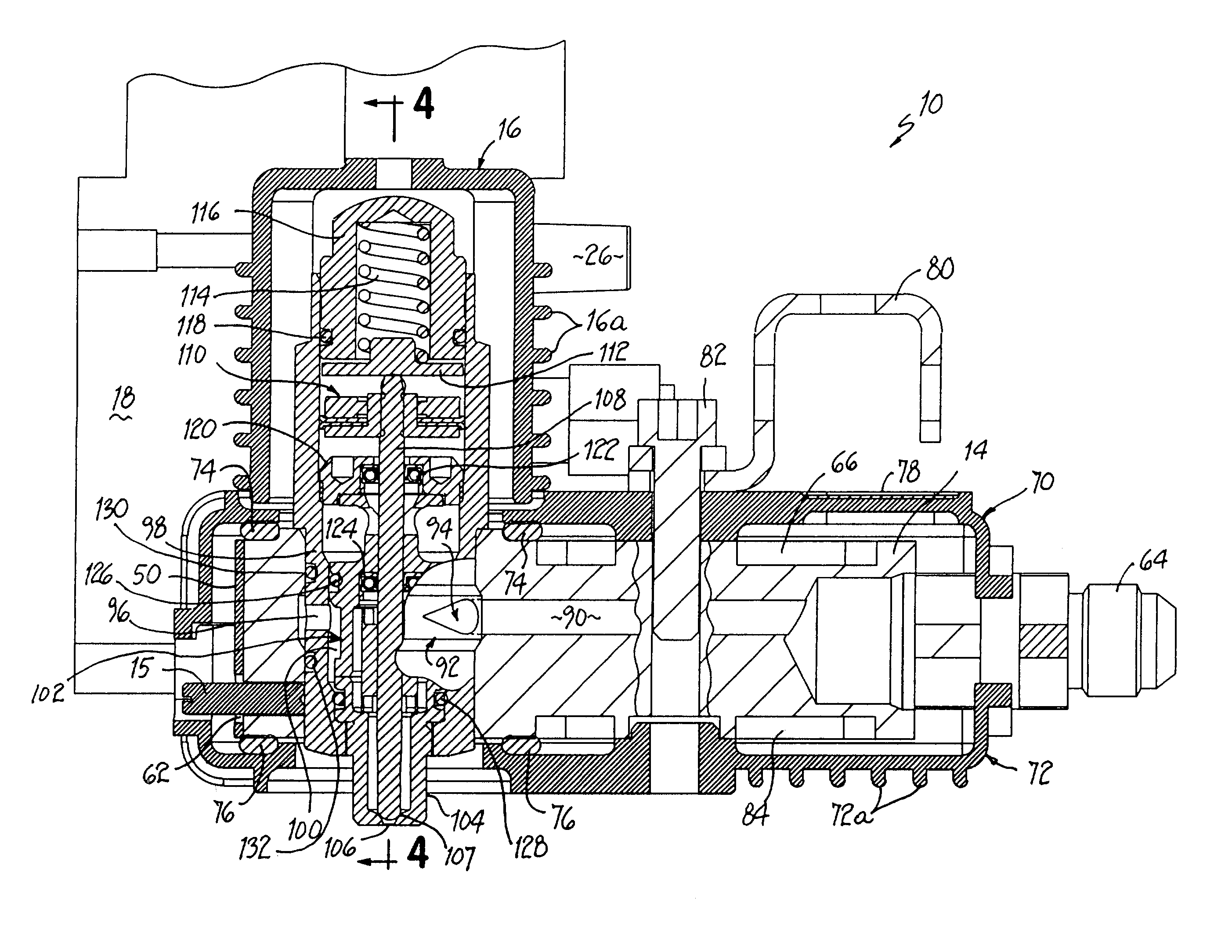
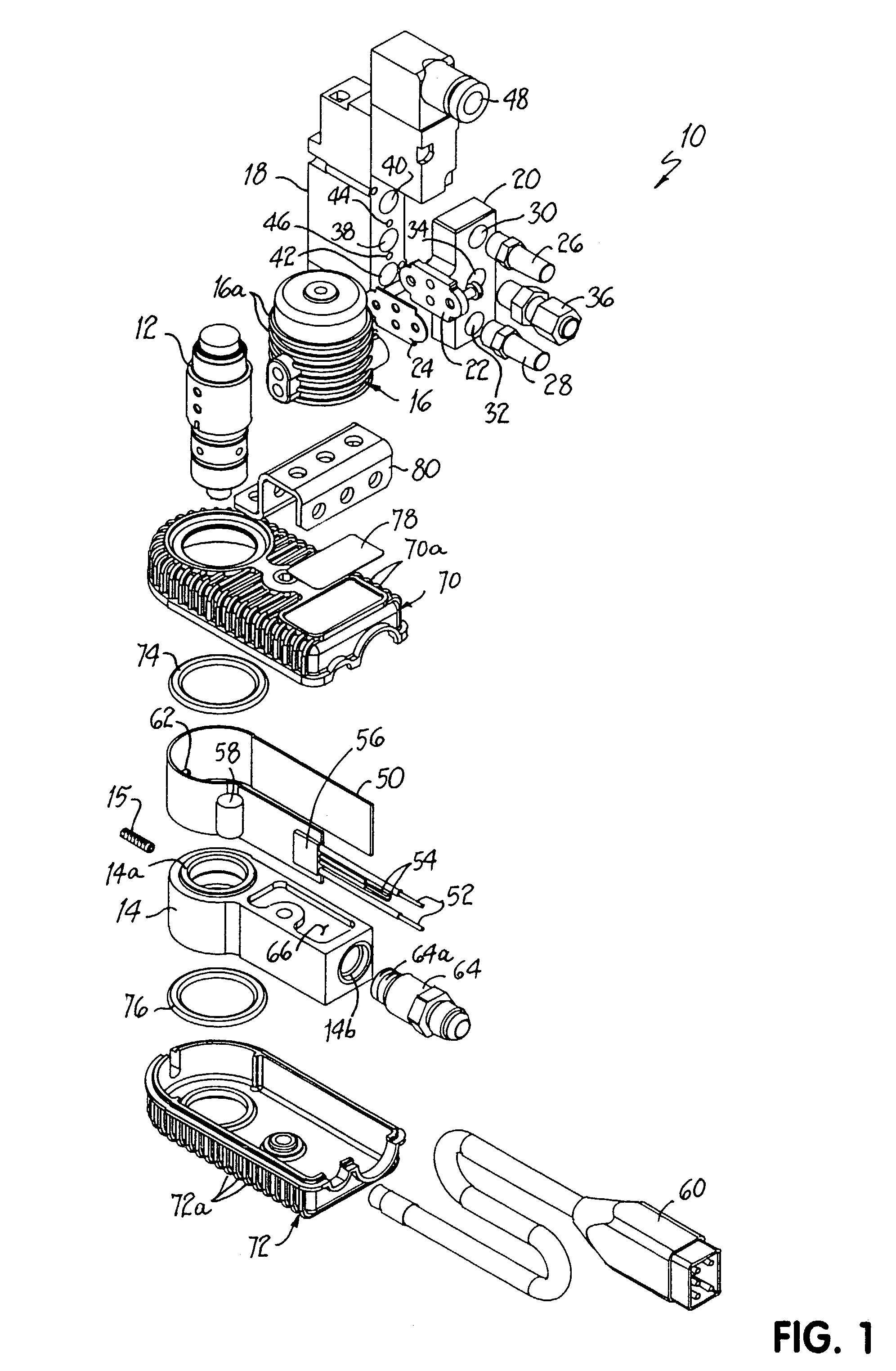
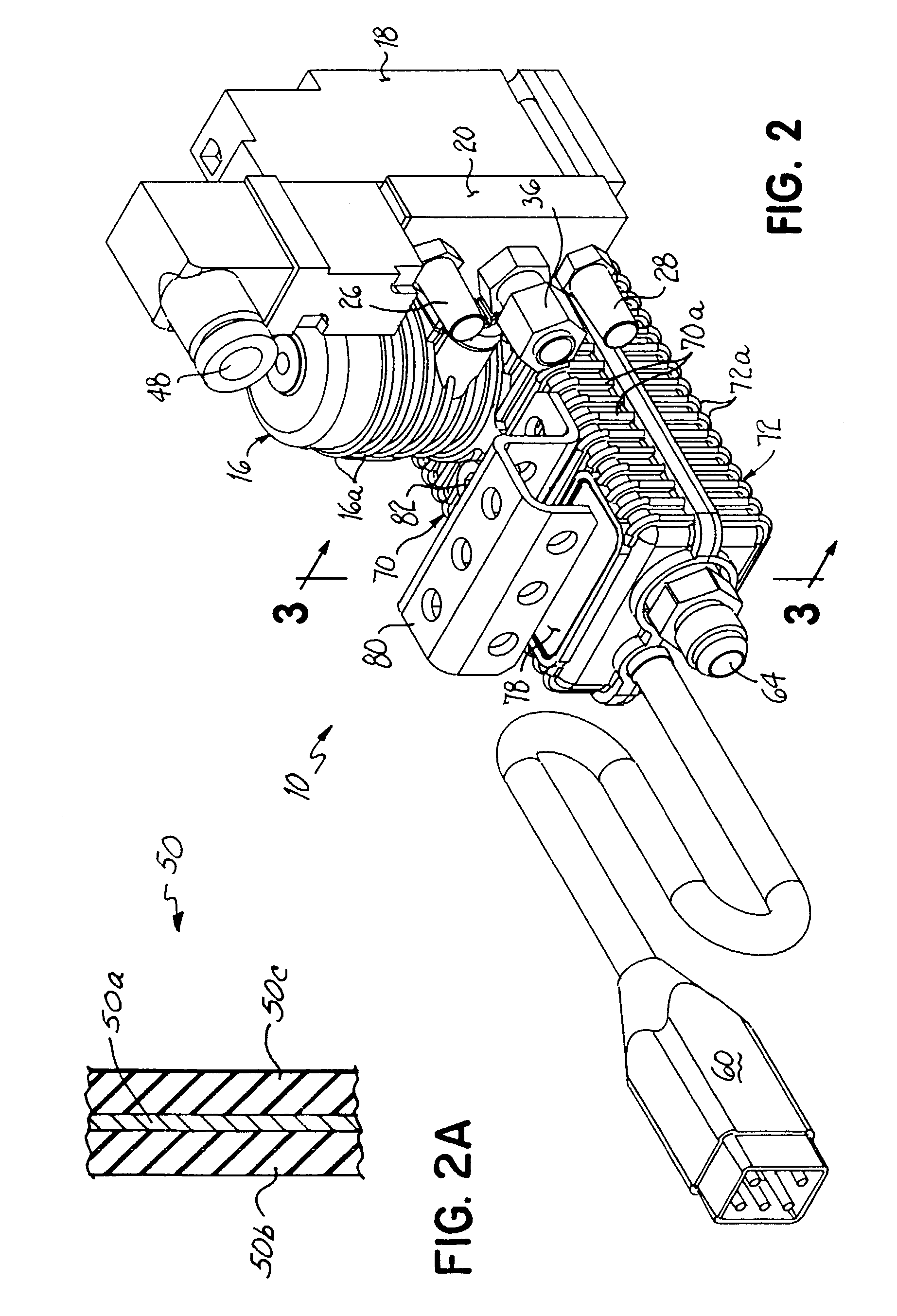
[0023]Referring to FIGS. 1 and 2, a hot melt adhesive dispensing apparatus 10 of the invention includes a dispensing module 12 and a liquid supply manifold 14. Dispensing module 12 is positioned within a mounting bore 14a of manifold 14 by a set screw 15. An air actuation cap 16 covers the upper end of dispensing module 12 and includes heat dissipating fins 16a. A solenoid valve 18 is connected to air actuation cap 16 by an adapter 20 having a flange 22. A seal 24 is disposed between air actuation cap 16 and adapter flange 22. As will be described in greater detail below, adapter 20 directs pressurized air into module 12 through air actuation cap 16 to actuate a valve within module 12 between open and closed positions.

[0024]Respective mufflers 26, 28 are connected within threaded exhaust ports 30, 32 of adapter 20. A central supply port 34 receives an air supply connector 36. Port 34 connects with supply port 38 of solenoid valve 18. Respective exhaust ports 30, 32 of adapter 20 con...


PUM


Abstract

Apparatus for dispensing viscous liquid, such as hot melt adhesive, includes a manifold, a dispensing module, a heater thermally coupled to the manifold, and thermally insulating cover structure secured around both the module and the manifold. Air gaps are formed between the cover structure and the heated components inside to further reduce heat transfer. The cover structure may also include heat dissipating fins. A supply connector associated with the manifold includes an interior flow passage, an exterior annular recess and at least one port communicating therebetween. A valve includes a valve seat having an orifice and a sealing surface located around the orifice. The valve further includes a valve stem movable between open and closed positions and having a recess in one end and a sealing edge located around the recess. A valve module includes an integrated heating element for providing localized heat to the adhesive immediately prior to dispensing.

Description

[0001]This application is a divisional of application Ser. No. 09 / 578,366, filed May 25, 2000 now U.S. Pat. No. 6,499,629 which is based on and claims the priority of Provisional Application Serial No. 60 / 136,461, filed May 28, 1999. The disclosures of these applications are hereby fully incorporated by reference herein.FIELD OF THE INVENTION[0002]The present invention generally relates to liquid dispensing technology and, more specifically, to adhesive dispensers using heated or unheated manifolds and valve modules to selectively dispense liquid adhesive.BACKGROUND OF THE INVENTION[0003]Existing hot melt adhesive dispensers operate at relatively high temperatures, such as above about 250° F. Present dispenser configurations have high temperature surfaces exposed to personnel. Considerable measures are taken to guard or insulate the dispensing equipment from nearby personnel. However, this also reduces the ease with which the equipment may be serviced by such personnel.[0004]Many ho...

Claims


Application Information

Patent Timeline
Patent Type & Authority Patents(United States)
IPC IPC(8): F16L53/00B67D5/62B67D7/00B05C5/00B05C5/02B05C11/10
CPCB05C5/001B05C11/1034B05C5/0225B05C5/02Y10T137/2196Y10T137/6606Y10T137/6525
Inventor COLANGELO, PAUL K.PETRECCA, PETER J.RAMSPECK, ALANWALKER, MICHAEL
Owner NORDSON CORP
Why Eureka
Try Eureka