Eureka AIR delivers breakthrough ideas for toughest innovation challenges, trusted by R&D personnel around the world.

Metallic gasket

a gasket and metal technology, applied in the direction of engine sealing, machine/engine, engine sealing arrangement, etc., can solve the problems of shortened gasket life, prone to fatigue failure, and difficult to secure the above-mentioned gap, so as to improve the processing accuracy of metal beads and enhance the cooling

Inactive Publication Date: 2006-04-11
JAPAN METAL GASKET CO LTD
View PDF29 Cites 63 Cited by
  • Summary
  • Abstract
  • Description
  • Claims
  • Application Information

AI Technical Summary

Benefits of technology

[0018]The present invention has been made with the above problems in mind, and has as its task to provide a metallic gasket capable of improving the processing accuracy of metal beads, and enhancing the cooling effects on the metallic gasket itself and the joint surfaces in which the metallic gasket is mounted.

Problems solved by technology

As a result of increased expansion coefficient by a difference of materials, there is a tendency that it is becoming difficult to secure the above-mentioned gap.
Therefore, it is necessary to adopt a material of high hardness, and in hard materials, internal stress concentrates in the portions of bending radius of the metal beads 52, 55, and when subjected to repetitive stress by vibration amplitude, they are liable to fatigue failure, and gasket lifetime is shortened.
Supposing an engine is made by aluminum, casting of aluminum is difficult and blowholes occur in casting.
An aluminum-made engine is liable to dents in transit.
Further, since the base plate 50 needs to be formed by a material of high hardness, it is difficult to improve the processing accuracy of the metal beads 52, 55 formed by bending the base plate 50.
By repeated load by repetition of operation and stoppage of the engine, after a long period of use, problems arise, such as a decrease in axial tension of the clamping bolts, changes with time of the base-plate bead 53 on the base plate 50, or deterioration in the elastic sealing material 54 of the concave portion of the bead; therefore, the seal surface pressure is likely to drop.
Such problems tend to come up particularly at overhanging parts on the outer side of the clamping bolts.
This is disadvantageous when the surface pressure decreases as described above.

Method used


Image

  • Metallic gasket
  • Metallic gasket
  • Metallic gasket

Examples


first embodiment

[0068]the present invention will be described with reference to the drawings.

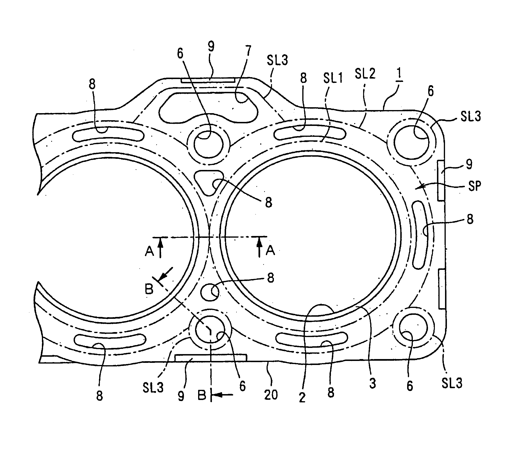
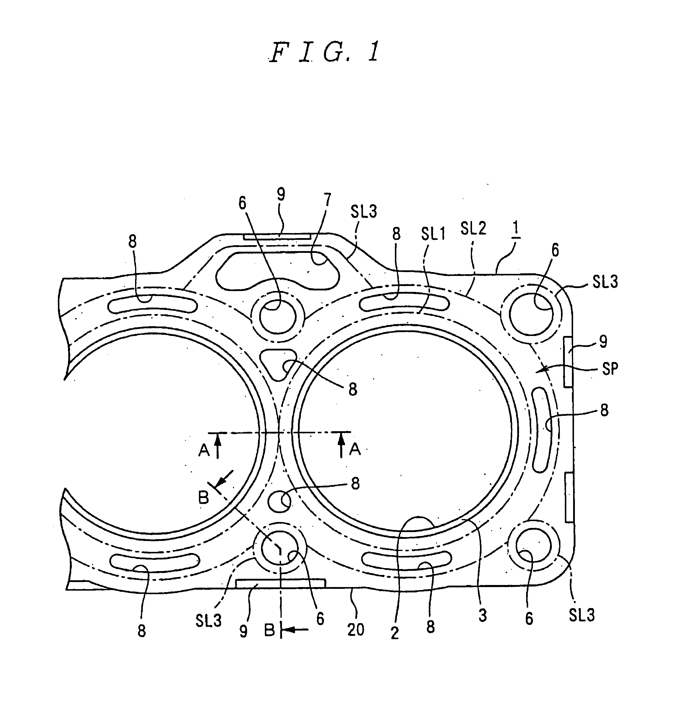
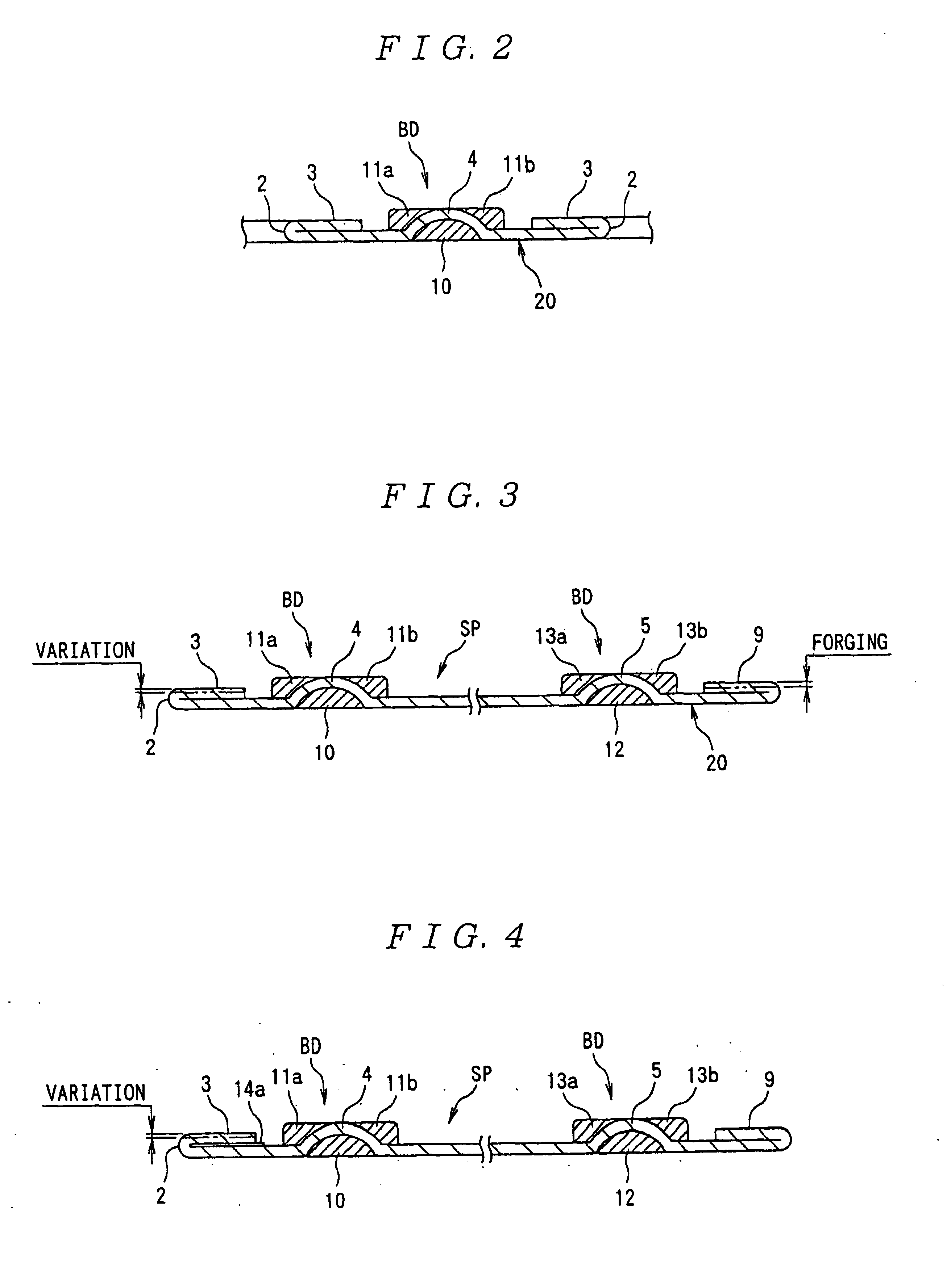
[0069]FIG. 1 is a plan view for explaining a metallic gasket according to the first embodiment of the present invention. FIG. 2 is a sectional view taken along the line A—A in FIG. 1. FIG. 3 is a sectional view taken along the line B—B in FIG. 3.

[0070]Description will next be made of the structure of the metallic gasket according to the first embodiment.

[0071]A metallic gasket 1 according to the first embodiment is an embodiment of a cylinder head gasket for an internal combustion engine. A base plate 20 of the metallic gasket 1 comprises thin metal plate, such stainless steel plate, soft steel plate, or steel plate. Here, the first embodiment will be described on the assumption that soft steel plate is used as a material for the base plate 20 with a view to providing a less expensive product.

[0072]As shown in FIG. 1, the base plate 20 is provided with a plurality of combustion chamber openings 2 aligned to...

second embodiment

[0100]the present invention will be described with reference to the drawings.

[0101]The basic structure of this second embodiment is the same as that of the first embodiment, but slightly differs in the structure of the bead from the first embodiment.

[0102]Beads are formed along the seal lines SL1 and SL2.

[0103]As shown in FIGS. 8 and 9, the bead BD according to this embodiment is a composite bead formed by a base-plate bead 6 as a full bead and rubber beads 8, 10.

[0104]The base-plate bead 6 is formed by bending the base plate in the through-thickness direction and the base-plate bead 6 is formed convex that is higher than the height of the thickness-increased portion 16.

[0105]The rubber bead comprises a first elastic sealing material part 10 filled in the concave portion of the base-plate bead 6, and a second elastic sealing material part 8 fixed to the convex portion side of the base-plate bead.

[0106]The first elastic sealing material part 10 is arranged such that the under surface...


PUM


Abstract

A metallic gasket comprising a base plate having a first thickness-increased portion 3 formed at a peripheral edge on a combustion chamber opening 3 side of a base plate, and a first seal line SL1 and a second seal line SL2 arranged on the outer side of said first thickness-increased portion 3. No openings other than a cooling water hole 8 exist between said two seal lines. Beads formed along said seal lines SL1 and SL2 each consist of a convex metal bead raised only upward from an upper surface of said base plate and a rubber bead made of an elastic sealing material fixed to a convex portion and a concave portion of said metal bead. This structure of said metallic gasket can improve a processing accuracy of said metal bead and also enhance cooling effects on said metallic gasket itself and said joint surfaces of an engine, between which said metallic gasket is disposed.

Description

[0001]This application is a national stage entry of international application no. PCT / JP02 / 11793, filed on Nov. 12, 2002, the entire specification, claims and drawings of which are incorporated herewith by reference.TECHNICAL FIELD[0002]The present invention relates to a metallic gasket and more particularly to a metallic gasket which is sandwiched in a joint between the joint surfaces of a cylinder block and a cylinder head of a water-cooled internal combustion engine, and which is capable of improving the cooling effect of the joint and the gasket itself.BACKGROUND ART[0003]Among conventional metallic gaskets aimed at improving the cooling effects of the parts between which a metallic gasket is sandwiched, there is one which is described in Japanese Patent Laid-Open No. 60-3465.[0004]As shown in FIGS. 21 and 22, this metallic gasket comprises a base plate 50 made of a thin, high-rigidity, elastic metal plate having a first metal bead 52 formed along a seal line SL1 encircling the ...

Claims


Application Information

Patent Timeline
Patent Type & Authority Patents(United States)
IPC IPC(8): F02F11/00F16J15/08
CPCF16J15/0818F16J2015/0843F16J2015/0875F16J2015/0868F16J2015/0856F02F11/00
Inventor UETA, KOSAKUWATANABE, HIDEO
Owner JAPAN METAL GASKET CO LTD
Why Eureka
Eureka Blog
Learn More