
Method of reducing photoelectric device leakage current in conjugated polymer and conjugated polymer composition

Active Publication Date: 2006-04-11
IND TECH RES INST
View PDF1 Cites 2 Cited by
  • Summary
  • Abstract
  • Description
  • Claims
  • Application Information

AI Technical Summary

Benefits of technology

[0006]In view of the disadvantage of the prior art mentioned above, an object of the invention is to provide a method of reducing photoelectric device leakage current caused by residual metal ions in conjugated polymer, which can reduce the leakage current in photoelectric devices and improve the stability.
[0010]In the present invention, the residual metal ions in the conjugated polymer material or the precursor thereof are chelated with a chelating agent, that is, the metal ions are captured by the chelating agent, therefore, the conductivity and mobility of the residual metal ions in an electric field are decreased, and in turn, the leakage current is reduced, allowing the device to have good stability. Furthermore, when the metal ions are chelated by a chelating agent, the activity of metal ions is decreased, avoiding a further reaction or oxidation of conjugated polymer material and thus increasing the stability of the material.

Problems solved by technology

However, there are many contamination sources, including the catalysts, reactants, and containers used in the synthesis of conjugated polymers and the environment.
Purification of conjugated polymer is difficult, therefore, after purification, residual metal ions may remain.
When an electric field is applied to a device comprising conjugated polymer, leakage current occurs due to the residual metal ions, reducing device efficiency.
A further reaction or oxidation of conjugated polymer material is possible due to residual metal ions, thus material stability is lowered and may lead to device failure.
It does not disclose the problem caused by residual metal ions and the method of the resolution.

Method used


Image

  • Method of reducing photoelectric device leakage current in conjugated polymer and conjugated polymer composition
  • Method of reducing photoelectric device leakage current in conjugated polymer and conjugated polymer composition
  • Method of reducing photoelectric device leakage current in conjugated polymer and conjugated polymer composition

Examples


preparation 1

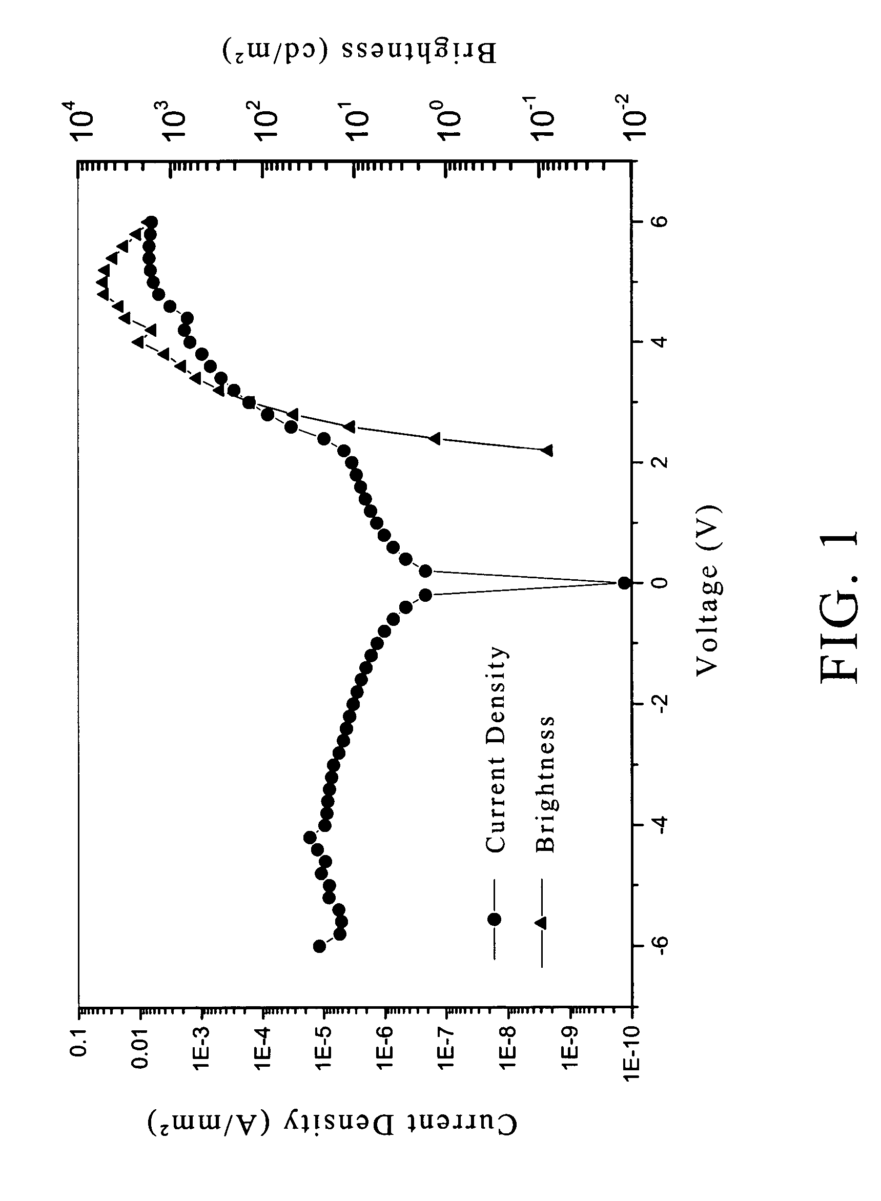
[0026]Conjugated polymer poly(2,3-dibutoxy-1,4-phenylene vinylene) (herein referred to as DB-PPV) was dissolved in dehydrated anisole in a concentration of 2.5 mg / cc under N2. The resulting solution was divided into four parts for the use in Comparative Example 1 and Examples 1 to 3. The molecular weight of the DB-PPV was about 860,000, and the distribution of molecular weight was 4.2. The metal ions and the amounts thereof contained in the DB-PPV are shown in Table 1.

[0027]

TABLE 1Metal ions and amounts thereof in the DB-PPVIonAmount of ion (ppm)Na23.6Mg13.1Al43.5K1238.0Ca128.8Cr2.8Mn1.2Fe65.9Co1.4Ni6.4Cu11.2Ba1.1Pb4.2Total1541content

example 1

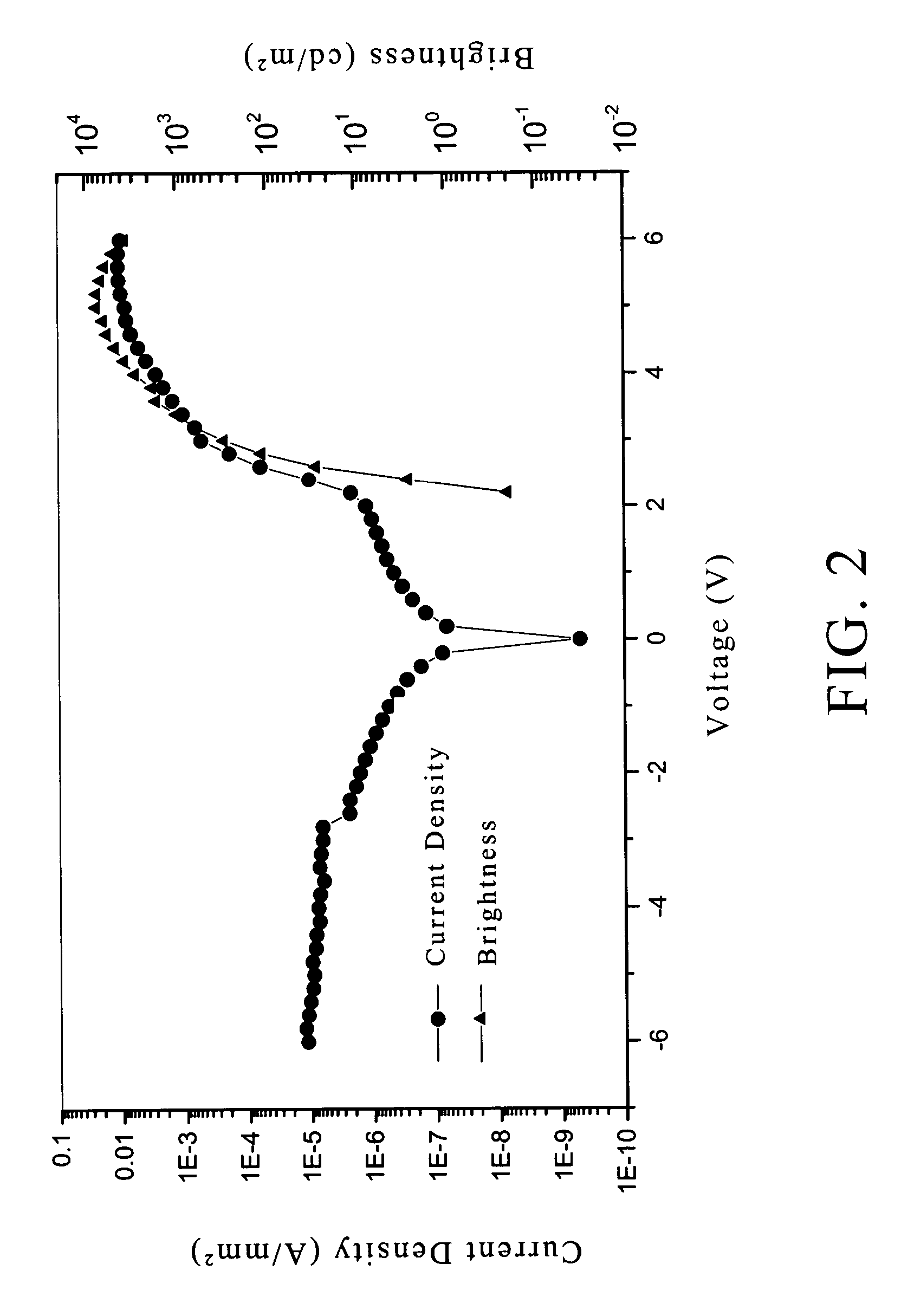
[0029]18-crown-6 as a chelating agent was added to the DB-PPV obtained from Preparation 1 in an amount of 5 wt % based on the weight of the DB-PPV polymer. PEDOT was spin-coated on a clean ITO glass sheet to form a layer of hole transferring material with a thickness of 60 nm. The DB-PPV solution containing the chelating agent was spin-coated on the PEDOT layer at 2000 rpm to form an electroluminescent layer with a thickness of 50 nm. The resultant was placed in a vacuum chamber and vacuumed to a pressure of 10−6 Torr, and then, a calcium layer as a cathode with a thickness of 50 nm was vapor-deposited over the electroluminescent layer. An aluminum layer as a protective layer was vapor-deposited over the cathode, and a device was accomplished. The photoelectric properties of the device were tested to obtain FIG. 2 showing the relations among current, voltage, and brightness.

example 2

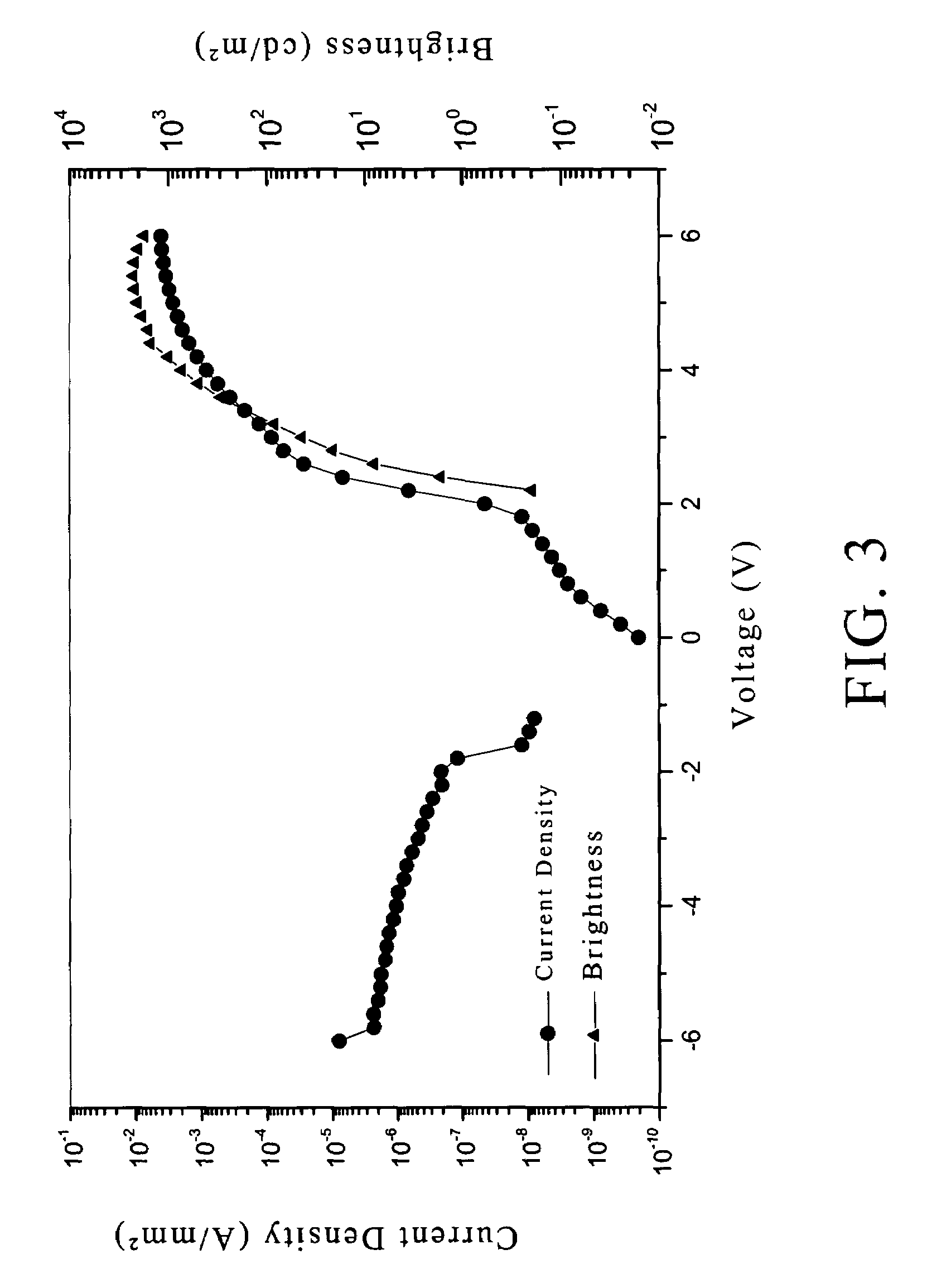
[0030]Example 2 was performed using the method same as Example 1, provided that 8-hydroxyquinoline was used as the chelating is agent instead of 18-crown-6. The photoelectric properties of the resulting device were tested to obtain FIG. 3.


PUM

PropertyMeasurementUnit
Fractionaaaaaaaaaa
Fractionaaaaaaaaaa
Fractionaaaaaaaaaa

Abstract

A method of reducing the photoelectric device leakage current caused by residual metal ions in conjugated polymer. A chelating agent is added to a conjugated polymer material, thereby the conductivity and mobility of metal ions under an electric field are reduced due to the chelation of metal ions by the chelating agent; therefore, the leakage current is reduced and the stability of devices is improved. Furthermore, the activity of metal ions is reduced after the metal ions are chelated by the chelating agent, improving the stability of the material and the devices. A conjugated polymer composition is also provided.

Description

BACKGROUND OF THE INVENTION[0001]1. Field of the Invention[0002]The present invention relates to a method of reducing photoelectric device leakage current caused by residual metal ions in conjugated polymer. The present invention also relates to a conjugated polymer composition.[0003]2. Description of the Related Art[0004]Conjugated polymer material is used widely in organic photoelectric devices, such as polymeric light emitting diodes, organic solar cells, organic transistors and the like. The purity of the conjugated polymer material is critical to the photoelectric properties of the devices. However, there are many contamination sources, including the catalysts, reactants, and containers used in the synthesis of conjugated polymers and the environment. Purification of conjugated polymer is difficult, therefore, after purification, residual metal ions may remain. When an electric field is applied to a device comprising conjugated polymer, leakage current occurs due to the residua...

Claims


Application Information

Patent Timeline
IPC IPC(8): C11D9/04C08F112/08H01L51/00H01L51/42H01L51/50
CPCH01L51/0003H01L51/002H01L51/0025H01L51/0038H01L51/0037Y02E10/549H01L51/424H01L51/5012H01L51/5048H10K71/30H10K71/12H10K71/311H10K85/114H10K85/1135H10K50/14H10K50/11H10K30/50H10K30/20
Inventor CHEN, KUO-YUTUAN, CHI-SHENTENG, WAN-JUNGCHANG, SHINN-JEN
Owner IND TECH RES INST
Learn More