Radiological imaging apparatus

a technology of radiological imaging and apparatus, applied in the field of radiological imaging apparatus, can solve the problems of reducing the amount of signal transmission substance, difficult to accurately measure and impaired correlation between the incident -ray energy and the signal generated by the doi detector, and achieves high efficiency and high-precision pet images

Inactive Publication Date: 2006-04-11
HITACHI LTD
View PDF22 Cites 53 Cited by
  • Summary
  • Abstract
  • Description
  • Claims
  • Application Information

AI Technical Summary

Benefits of technology

[0015]It is an object of the present invention to provide a radiological imaging apparatus that determines the locations reached by radiation with increased precision and enhances the accuracy of images to be generated.
[0016]The present invention to attain the above-described object is characterized by comprising an image pickup device, which comprises a plurality of radiation detectors for detecting radiation from a subject, wherein the radiation passing through a first radiation detector is to be detected by a second radiation detector. Since the second radiation detector is provided to detect the radiation passing through the first radiation detector, the locations reached by radiation (locations at which radiation is detected) can be confirmed, with increased precision, in the direction of the depth from the first radiation detector opposing the subject. As a result, a highly accurate image depicting the interior of the subject's body can be obtained.
[0020]The present invention makes it possible to find the sequence of unscattered γ-ray attenuation (scatter sequence) in accordance with three or more detection signals output within a preselected period of time and the positional information about three or more radiation detectors that generated the detection signals, and determine the position and direction of γ-ray initial incidence. In marked contrast to determining the γ-ray initial incidence position in a random manner, the present invention is capable of locating unscattered γ radiation with high efficiency and generating highly accurate tomograms.
[0022]The present invention determines the attenuation sequence (scatter sequence) of one of paired γ-rays in accordance with the positional information about the remaining paired γ-ray, and determines the position and direction of γ-ray initial incidence on a radiation detector. More specifically, the positional information about each radiation detector detecting a first one of paired γ-rays and the positional information about a radiation detector detecting the remaining paired γ-ray are used to estimate two or more possible attenuation sequences of the first one of the paired γ-rays. The estimated attenuation sequences are examined to choose the one that exhibits the proper correlation between the scatter angle and energy detection value of the first one of the paired γ-rays. The γ-ray attenuation sequence is determined in this manner. As a result, the position of initial γ-ray incidence on a radiation detector (the position of a radiation detector related to the first γ-ray attenuation) is determined. Consequently, it is possible to conclude that a γ-ray generation source (diseased area) exists on a straight line (direction of initial incidence) joining the located radiation detector and the radiation detector detecting the remaining paired γ-ray. In marked contrast to determining the γ-ray initial incidence position in a random manner, the present invention is therefore capable of locating unscattered γ radiation with high efficiency and generating highly accurate PET images.
[0024]When the detection signals of three or more radiation detectors are simultaneously counted (output within the specified period of time), the present invention determines the γ-ray attenuation sequence (scatter sequence) in accordance with the positional information about the three or more detection signals and the energy detection values from the three or more radiation detectors, and determines the position and direction of γ-ray incidence on a radiation detector. More specifically, the above-mentioned positional information is first used to estimate two or more possible sequences of γ-ray attenuation, and the estimated sequences are checked to choose the one that exhibits the proper correlation with the above-mentioned energy detection values. In accordance with the determined γ-ray initial incidence position and the above energy detection values, the direction of γ-ray initial incidence can be determined. In marked contrast to determining the γ-ray initial incidence position in a random manner, the present invention is therefore capable of locating unscattered γ radiation with high efficiency and generating highly accurate PET images.

Problems solved by technology

However, the use of a DOI detector involves image deterioration, which is caused by a decrease in the amount of signal transmission substance.
When the energy spectrum is spread, the correlation between the incident γ-ray energy and the signal generated by a DOI detector is impaired.
As a result, this makes it difficult to accurately measure the incident γ-ray energy.
If incident γ-ray energy measurements cannot be accurately made, it is difficult to remove scattered radiation contained in incident γ-rays.
This can cause PET image deterioration.
The radiation detector's detection efficiency deteriorates with time.
However, the deterioration characteristic varies from one radiation detector to another.
In PET or SPECT examination in which the number of photons incident on each radiation detector is measured, correct measurement cannot be made if the detection efficiency varies from one radiation detector to another.
As explained above, the use of radiological imaging apparatuses entails an enormous amount of time and labor because they require their radiation detectors to be checked for detection efficiency variation in order to maintain examination accuracy.

Method used


Image

  • Radiological imaging apparatus
  • Radiological imaging apparatus
  • Radiological imaging apparatus

Examples


embodiment 1

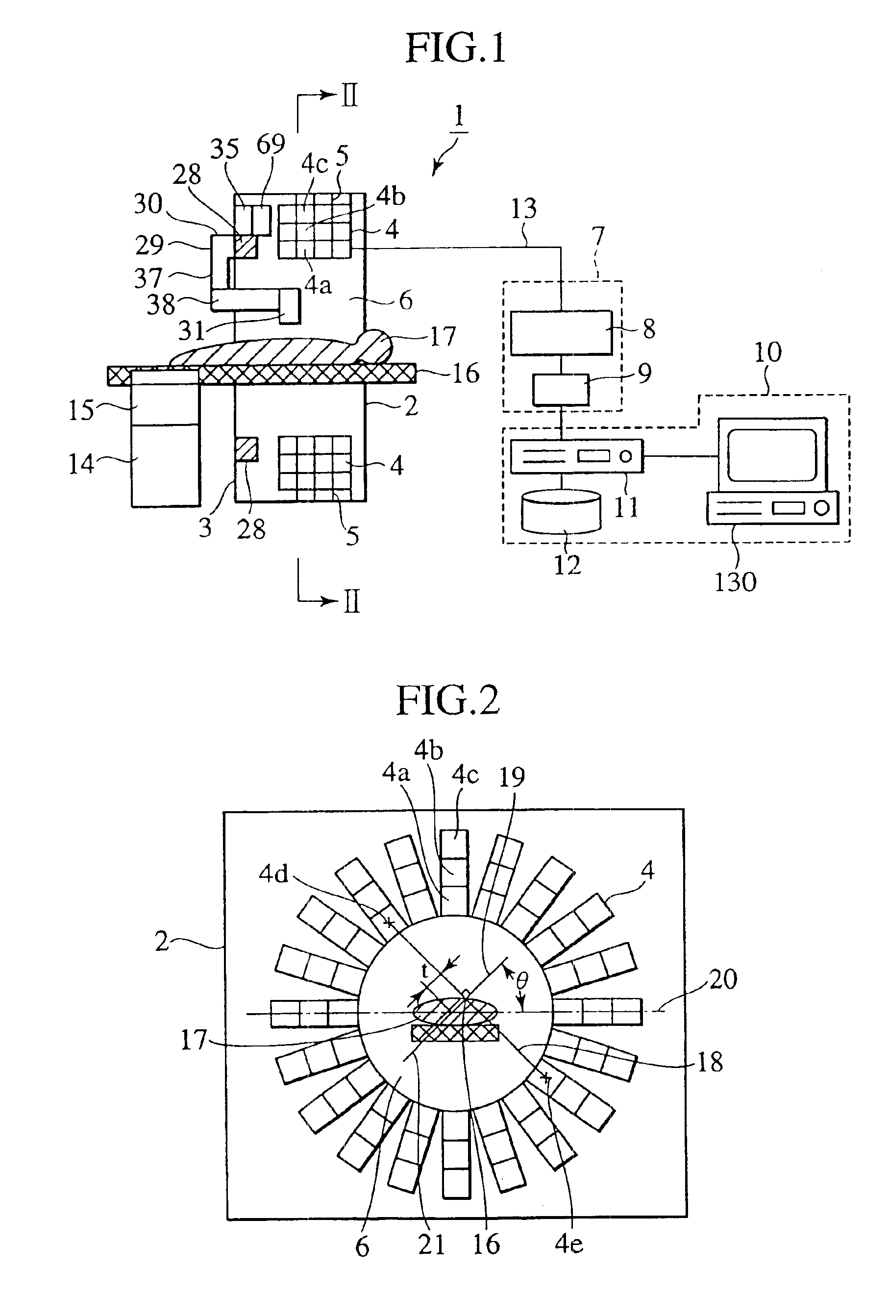
[0052]A radiological imaging apparatus according to a preferred embodiment of the present invention will be described below with reference to FIGS. 1 and 2. A radiological imaging apparatus 1 of Embodiment 1 is used for PET examination. This apparatus comprises an image pickup device 2, a signal processor 7, a tomogram generator 10, a medical examinee-holding device 14, a calibrated radiation source circumferential transfer unit 37, and a drive controller 35.

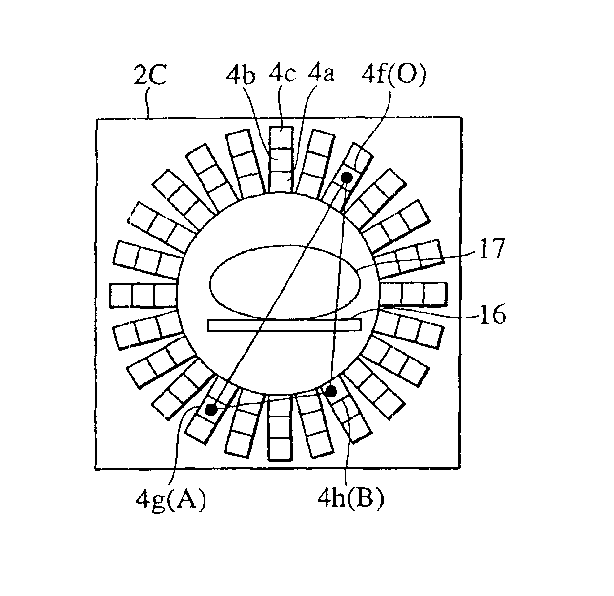
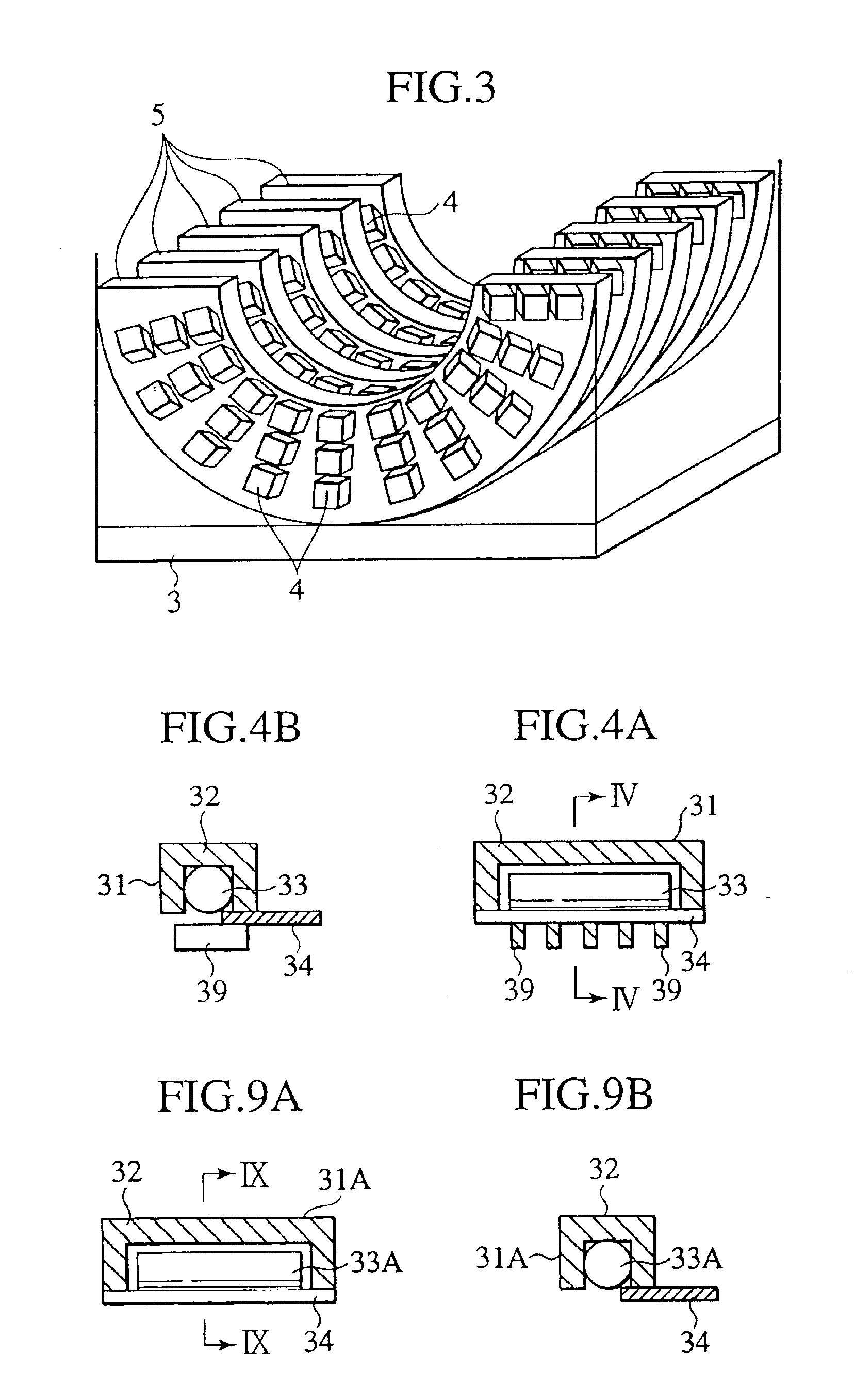
[0053]The image pick device 2 has a casing 3, a large number of radiation detectors 4, and a large number of radiation detector support plates 5. The casing 3 has an opening (through-hole) 6 into which a medical examinee or a subject is to be inserted. A large number of the radiation detectors (e.g., 10,000 radiation detectors in total) 4 are positioned around the circumference of the through-hole 6 and arranged in the axial direction of the through-hole 6. As shown in FIG. 2, the innermost radiation detectors 4 are circularly d...

embodiment 2

[0083]A radiological imaging apparatus of another embodiment (Embodiment 2) of the present invention will be described with reference to FIG. 8. The radiological imaging apparatus 1A of Embodiment 2 is used for SPECT examination. This apparatus 1A comprises an image pickup device 2A in place of the image pickup device 2 for the radiological imaging apparatus 1 and a signal processor 7A instead of the signal processor 7 for the radiological imaging apparatus 1. The other components of the radiological imaging apparatus 1A are the same as for the radiological imaging apparatus 1. The signal processor 7A includes a γ-ray discriminator 8A and a counter 36 connected to the γ-ray discriminator 8A, and is provided for each radiation detector 4. The γ-ray discriminator 8A has a filter energy setting of 120 keV although the filter energy setting for the γ-ray discriminator 8 in Embodiment 1 is 400 keV. The image pickup device 2A differs from the image pickup device 2 in that a collimator 27 ...

embodiment 3

[0093]A radiological imaging apparatus of another embodiment (Embodiment 3) of the present invention will be described with reference to FIGS. 10 and 11. The radiological imaging apparatus 1B of Embodiment 3 is used for X-ray CT examination (in which an X-ray emission from an X-ray source 60 passes through the body of a medical examinee and is detected by radiation detectors) and PET examination. This apparatus 1B comprises an image pickup device 2B in place of the image pickup device 2 for the radiological imaging apparatus 1 and a signal processor 7A instead of the signal processor 7 for the radiological imaging apparatus 1. The other components of the radiological imaging apparatus 1B are the same as for the radiological imaging apparatus 1. The image pickup device 2B uses a calibrated radiation source circumferential transfer unit 37B in place of the calibrated radiation source circumferential transfer unit 37 that is used for the image pickup device 2. The calibrated radiation ...


PUM

PropertyMeasurementUnit
energyaaaaaaaaaa
energyaaaaaaaaaa
energyaaaaaaaaaa

Abstract

A radiological imaging apparatus of the present invention comprises an image pickup device and a medical examinee holding device that is provided with a bed. The image pickup device includes a large number of radiation detectors and radiation detector support plates. A large number of radiation detectors are mounted around the circumference of a through-hole and arranged in the axial direction of the through-hole. The radiation detectors are arranged in three layers formed radially with respect to the center of the through-hole and mounted on the lateral surfaces of the radiation detector support plates. Since the radiation detectors are not only arranged in the axial direction and circumferential direction of the through-hole but also arrayed in the radial direction, it is possible to obtain accurate information about a γ-ray arrival position in the radial direction of the through-hole (the positional information about a radiation detector from which a γ-ray image pickup signal is output). The use of accurate information about γ-ray arrival increases the tomogram accuracy. As a result, the present invention enhances the tomogram accuracy, that is, the PET examination accuracy.

Description

[0001]This application is a continuation of application Ser. No. 10 / 270,151, filed Oct. 15, 2002, the subject matter of which is incorporated by reference herein.BACKGROUND OF THE INVENTION[0002]The present invention relates to a radiological imaging apparatus, and more particularly to a radiological imaging apparatus ideally applicable to X-ray computed tomography, positron emission computed tomography (hereinafter referred to as “PET”), single-photon emission computed tomography (hereinafter referred to as “SPECT”), digital X-ray examination flat panel detector, and similar equipment.[0003]Radiological imaging is a non-invasive imaging technology to examine physical functions and conformation of a medical examinee as a subject. Typical radiological imaging devices are X-ray computed tomography, digital X-ray examination, PET, and SPECT devices.[0004]PET is a method for administering a radiopharmaceutical (hereinafter referred to as a “PET pharmaceutical”) containing positron-emitt...

Claims


Application Information

Patent Timeline
Patent Type & Authority Patents(United States)
IPC IPC(8): G01T1/164A61B6/00G01N23/00G01N23/04G01T1/29G21K1/12H05G1/60
CPCG01N23/046G01T1/1611G01T1/1615G01T1/1647G01T1/2985G01T1/242A61B6/037G01T1/249G01N2223/612G01N2223/419
Inventor KOJIMA, SHINICHIOKAZAKI, TAKASHIUENO, YUUICHIROUUMEGAKI, KIKUOAMEMIYA, KENSUKETAKEUCHI, KAZUHIROKITAGUCHI, HIROSHIYOKOI, KAZUMAYANAGITA, NORIHITO
Owner HITACHI LTD
Why Eureka
Try Eureka