Cryogenic x-ray source device

a source device and x-ray technology, applied in the field of miniature x-ray source devices, can solve the problems of limiting the application of such a device in the patient's body, reducing and increasing the heat dissipation rate, so as to improve the control of the working temperature of the anod

Active Publication Date: 2006-04-11
NUCLETRON OPERATIONS
View PDF6 Cites 6 Cited by
  • Summary
  • Abstract
  • Description
  • Claims
  • Application Information

AI Technical Summary

Benefits of technology

[0013]It is an object of the present invention to provide a miniature X-ray source device according to the above preamble having further limited cons...

Problems solved by technology

Although with such cooling means a higher rate of heat dissipation and subsequently a decrease in the working temperature of the anode can be obtained they require significant cooling capacity of the cooling means before an efficient cooling of the anode is obtained.
Furthermore with a construction like suggested in U.S. Pat. No. 6,319,188 the outer dimensions of the X-r...

Method used


Image

  • Cryogenic x-ray source device
  • Cryogenic x-ray source device
  • Cryogenic x-ray source device

Examples


first embodiment

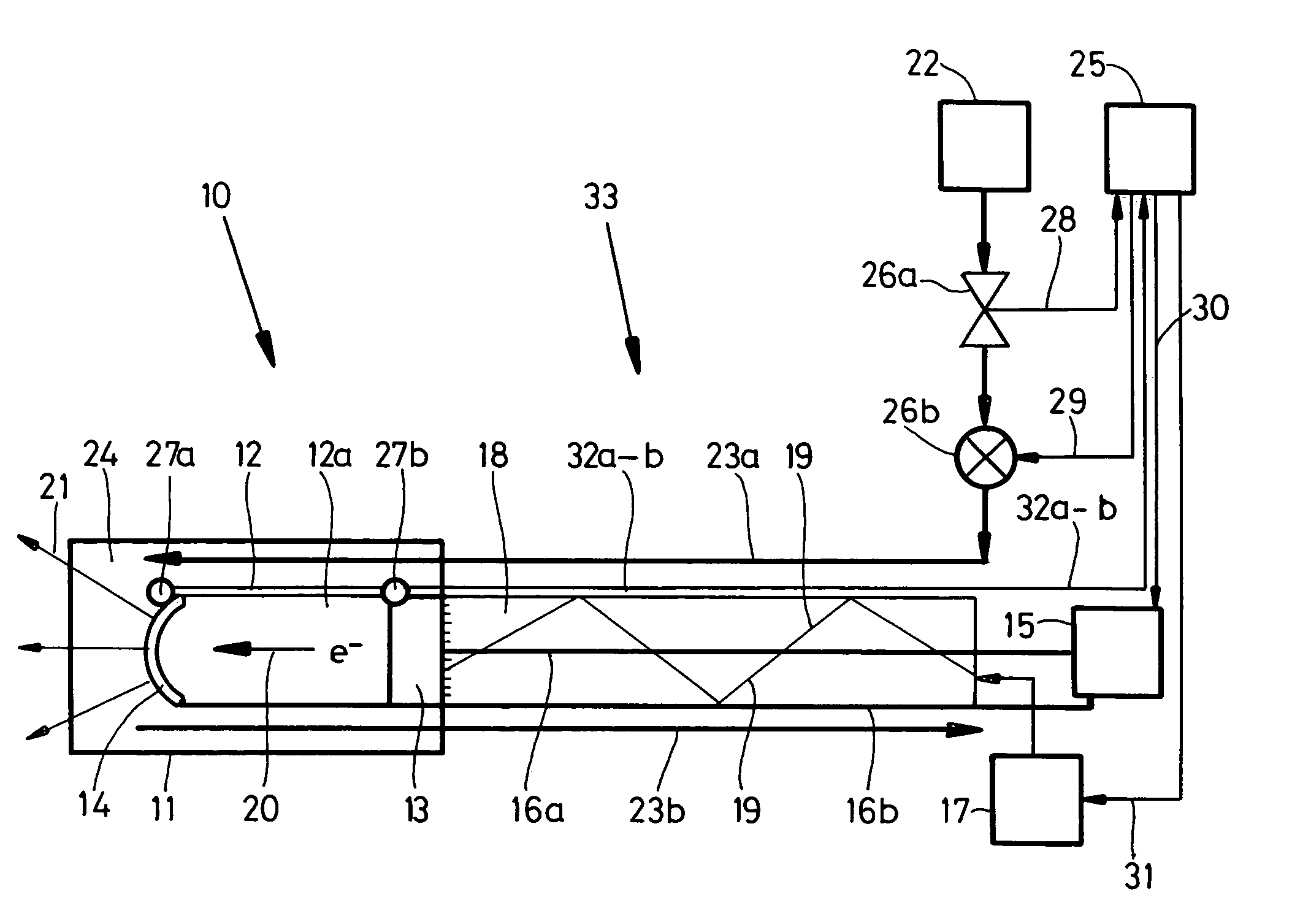
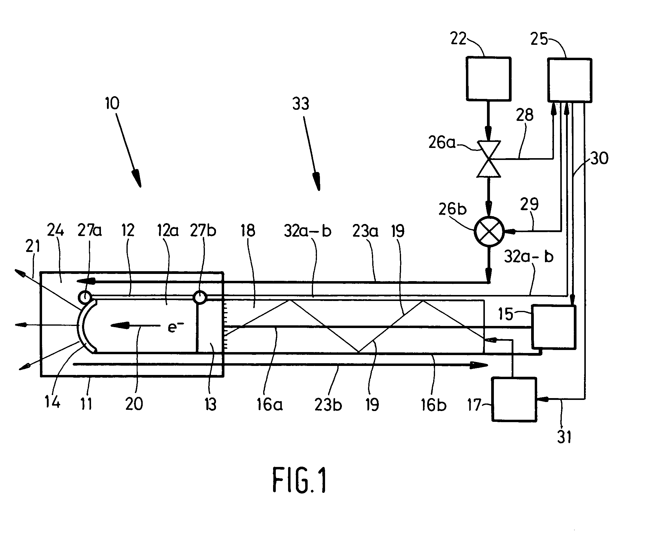
[0042]In FIG. 1 miniature X-ray source device according to the invention is disclosed. The miniature X-ray source device 10 comprises a housing 11 wherein a vacuum tube 12 is accommodated. Within said vacuum tube a cathode 13 and an anode 14 are positioned at some distance from each other. The vacuum tube 12 forms a cavity or chamber 12a which is evacuated to a desired vacuum level necessary for a proper operation of the miniature X-ray tube.

[0043]The cathode 13 is connected to light emitting means 17 in this embodiment constructed as a laser device or LED device or a similar light emitting component. These means emits a light beam 19 which travels through an optical fibre 18 of a considerable length which is connected to the cathode 13.

[0044]The light 19 emitted by said light-emitting means 17 impinge on the cathode 13 and free electrons 20 are emitted from said cathode material 13.

[0045]The miniature X-ray source device 10 is also provided with electric field generating means 15 f...

second embodiment

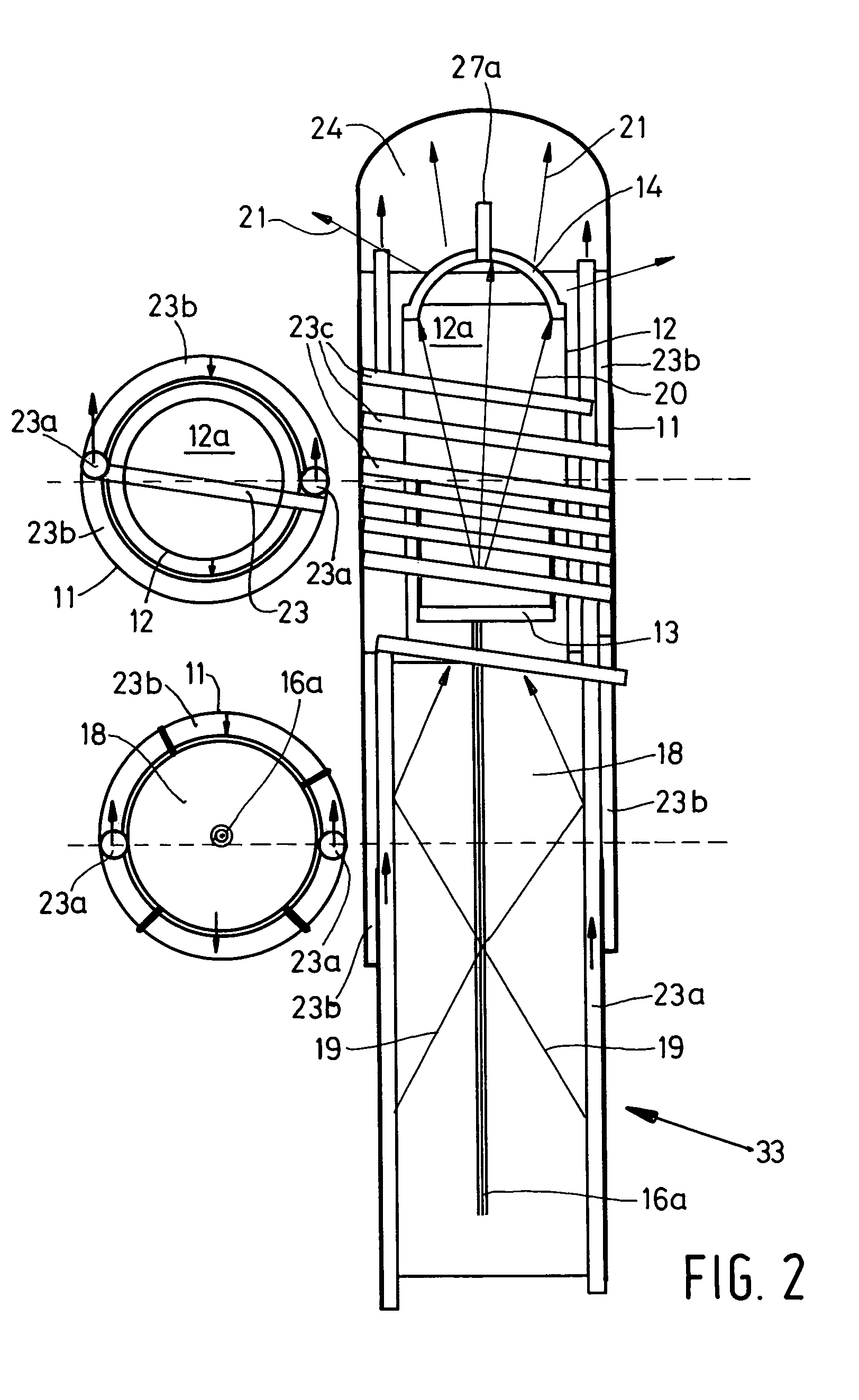
[0064]In FIG. 2 the miniature X-ray source device according to the invention is disclosed wherein the cooling means 22 are not connected by means of a straight supply passageway 23a and a straight exhaust passageway 23b as in FIG. 1 but whereas the supply passageway 23a is accommodated in one or more helical X-ray transparent windings 23c around the vacuum tube 12. This improved embodiment causes also a beneficial cooling effect on the cathode 13 further improving the versatility of the miniature X-ray source device according to the invention but moreover further expanding the life span of the miniature X-ray source device. In this embodiment two supply passageway 23a are used one of the ending straight into the expansion chamber 24 and the other supply passageway 23a accommodated in one or more helical X-ray transparent windings 23c around the vacuum tube 12. The exhaust passageway 23b is in this embodiment formed by an interstice present between the housing 11 and the vacuum tube ...


PUM


Abstract

The invention relates to a miniature X-ray source device connected to a distal end of a guiding wire for insertion towards a desired location within an animal body for effecting radiation therapy, said X-ray source device at least comprising a vacuum tube accommodated in said housing containing a cathode and an anode spaced apart at some distance from each other; electron freeing means for freeing electrons from the cathode; electric field means for applying during use a high-voltage electric field between said cathode and said anode for accelerating said free electrons; said vacuum tube being at least partly transparent to X-ray radiation emitted by said anode, as well as cooling means for cooling at least said anode.
It is an object to provide a miniature X-ray source device having further limited constructional dimensions and an improved control of the working temperature of at least the anode and hence the working conditions of the miniature X-ray source device.
According to the invention the miniature X-ray source device is hereto characterised in that said cooling means are cryogenic cooling means. More in particular in a specific embodiment of said miniature X-ray source device said cooling means comprise at least one supply passageway for supplying pressurized gas towards said anode and at least one exhaust passageway for exhausting said pressurized gas from said anode, said supply passageway and said exhaust passageway being interconnected by means of an expansion chamber surrounding at least partly said anode.

Description

[0001]This Non-provisional application claims priority under 35 U.S.C. § 119(a) on Patent Application No(s). 03077134.9 filed in Europe on Jun. 30, 2003, the entire contents of which are hereby incorporated by reference.BACKGROUND OF THE INVENTION[0002]1. Field of the Invention[0003]The invention relates to a miniature X-ray source device connected to a distal end of a guiding wire for insertion towards a desired location within an animal body for effecting radiation therapy, said X-ray source device at least comprising a vacuum tube accommodated in said housing containing a cathode and an anode spaced apart at some distance from each other; electron freeing means for freeing electrons from the cathode; electric field means for applying during use a high-voltage electric field between said cathode and said anode for accelerating said free electrons; said vacuum tube being at least partly transparent to X-ray radiation emitted by said anode, as well as cooling means for cooling at le...

Claims


Application Information

Patent Timeline
IPC IPC(8): H01J35/12A61N5/00A61N5/10H01J35/06H01J35/32
CPCA61N5/1001H01J35/065H01J35/12H01J35/32A61N2005/005H01J2235/1204H01J2235/186H01J2235/1216H01J2235/122H01J2235/127H01J2235/1275H01J2235/1287H01J2235/1212H01J35/186H01J35/13
Inventor KINDLEIN, JOHANN
Owner NUCLETRON OPERATIONS
Why Eureka
Try Eureka